St173cpbf series, Vishay high power products – C&H Technology ST173CPBF Series User Manual
Page 8
Document Number: 94366
For technical questions, contact: [email protected]
www.vishay.com
Revision: 29-Apr-08
7
ST173CPBF Series
Inverter Grade Thyristors
(Hockey PUK Version), 330 A
Vishay High Power Products
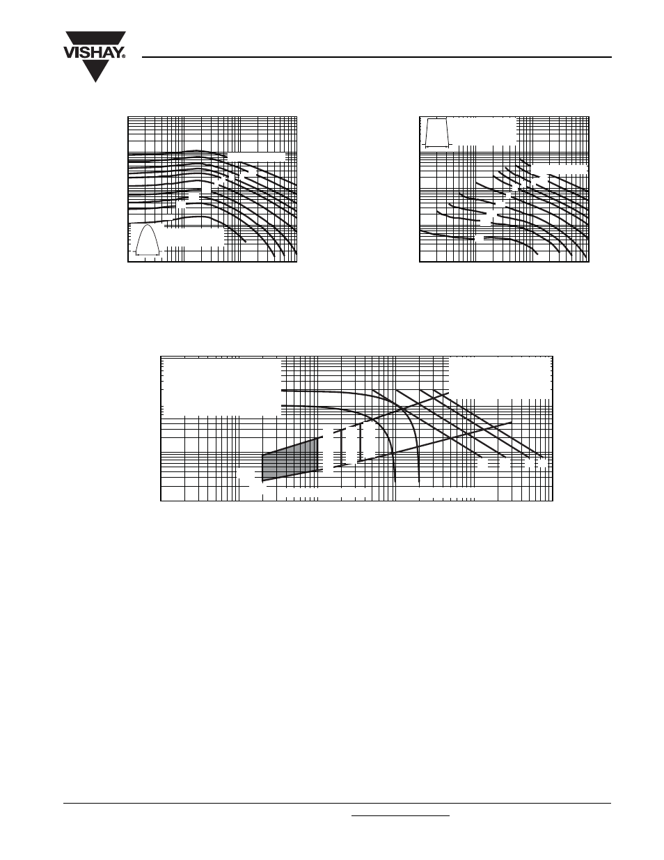
Fig. 16 - Maximum On-State Energy Power Loss Characteristics
Fig. 17 - Gate Characteristics
Pulse Basewidth (µs)
Peak On-State Current (A)
10
100
1000
10 000
10
100
1000
10 000
t
p
ST173C..C Series
Sinusoidal pulse
100 000
0.1
0.2
0.5
2 3
1
5
10
20 joules per pulse
0.3
Pulse Basewidth (µs)
Peak On-State Current (A)
10
100
1000
10 000
10
100
1000
10 000
100 000
0.1
0.2
0.5
2
3
1
5 10
20 joules per pulse
t
p
ST173C..C Series
Rectangular pulse
dI/dt = 50 A/µs
0.3
0.1
1
10
100
0.001
Instantaneous Gate Current (A)
Instantaneous Gate Voltage (V)
0.01
0.1
1
10
100
(b)
V
GD
I
GD
(1)
(2)
(3)
Device: ST173C..C Series
(4)
Frequency limited by P
G(AV)
(1) P
GM
= 10 W, t
p
= 20 ms
(2) P
GM
= 20 W, t
p
= 10 ms
(3) P
GM
= 40 W, t
p
= 5 ms
(4) P
GM
= 60 W, t
p
= 3.3 ms
Rectangular gate pulse
a) Recommended load line for
rated dI/dt: 20 V, 10
Ω; t
r
≤ 1 µs
b) Recommended load line for
≤ 30 % rated dI/dt: 10 V, 10 Ω
t
r
≤ 1 µs
(a)
T
J
= 40 °C
T
J
= 25 °C
T
J
= 125 °C