Protection function timing diagrams – C&H Technology PS22052 User Manual
Page 7
PS22052
Intellimod™ Module
Dual-In-Line Intelligent Power Module
5 Amperes/1200 Volts
Powerex, Inc., 200 E. Hillis Street, Youngwood, Pennsylvania 15697-1800 (724) 925-7272
6
Rev. 10/05
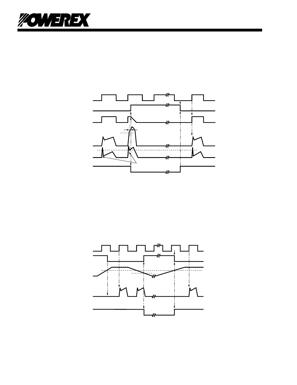
Protection Function Timing Diagrams
A1
A4
A5
A2
SC
A7
A3
SET
RESET
RC FILTER TIME
CONSISTANT DELAY
SC REFERENCE VOLTAGE
A6
A8
LOWER-SIDE
CONTROL INPUT
PROTECTION
CIRCUIT STATE
INTERNAL IGBT GATE
OUTPUT CURRENT IC
SENSE VOLTAGE ON
THE SHUNT RESISTOR
FAULT OUTPUT FO
Short-Circuit Protection (N-side only, with external shunt resistor and CR filter)
A1: Normal operation – IGBT turn on and conducting current.
A2: Short-circuit current detected (SC trigger).
A3: IGBT gate hard interrupted.
A4: IGBT turn off.
A5: FO output with a fixed pulse width (determined by the external capacitance CFO).
A6: Input “L” – IGBT off.
A7: Input “H” – IGBT on is blocked during the FO output period.
A8: IGBT stays in off state.
B1
B4
B5
B2
UVDt
B7
B3
SET
RESET
RESET
UVDr
B6
CONTROL INPUT
PROTECTION
CIRCUIT STATE
CONTROL SUPPLY
VOLTAGE VD
OUTPUT CURRENT IC
FAULT OUTPUT FO
Under-Voltage Protection (N-side, UVD)
B1: Control supply voltage rise – After the voltage level reaches UVDr, the drive circuit begins to work
at the rising edge of the next input signal.
B2 : Normal operation – IGBT turn on and conducting current.
B3: Under-voltage trip (UVDt).
B4: IGBT turn off regardless of the control input level.
B5: FO asserted during the period from minimum pulse width or until control supply recover to UVDr.
B6: Under-voltage reset (UVDr).
B7: Normal operation – IGBT turn on and conducting current.