Datasheet, D2to20, Vishay sfernice – C&H Technology D2TO20 User Manual
Page 2
www.vishay.com
For technical questions, contact: [email protected]
Document Number: 51055
36
Revision: 24-Nov-08
D2TO20
Vishay Sfernice
Surface Mounted Power Resistor
Thick Film Technology
FEATURES
• 20 W at 25 °C case temperature
• Surface mounted resistor - TO-263 (D
2
PAK) style
package
• Wide resistance range from 0.01 Ω to 550 kΩ
• Non Inductive
• RoHS compliant
• Resistor isolated from metal tab
• Solder reflow secure at 270 °C/10 s
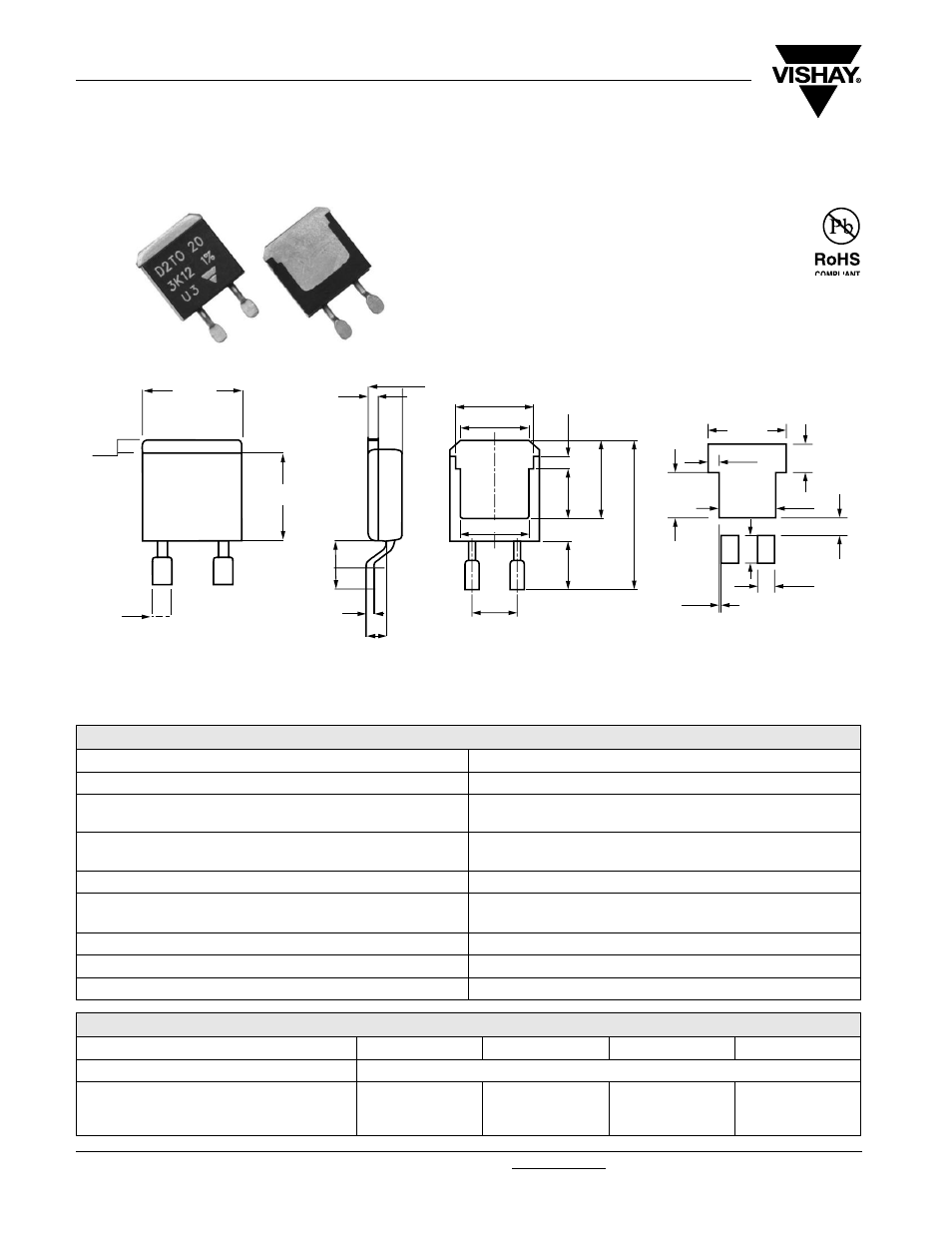
DIMENSIONS in millimeters
Notes
• For the asssembly on board, we recommend the lead (Pb)-free thermal profile as per J-STD-020C
• Power dissipation is 2.8 W at an ambient temperature of 25 °C when mounted on a double sided copper board using FR4 standard, 70 µm of
copper, 39 x 30 x 1.6 mm.
ELECTRICAL SPECIFICATIONS
Resistance Range
0.01
Ω to 550 kΩ
Tolerances (Standard)
± 1 % to 10 %
Power Rating and Thermal Resistance
20 W at 25 °C (case temperature)
R
TH (j - c)
: 6.5 °C/W
Temperature Coefficient
See Special Features table
Standard: ± 150 ppm/°C
Limiting Element Voltage U
L
250 V
Dielectric Strength IEC 60115-1
2000 V
rms
- 1 min - 10 mA max.
(between terminals and board)
Insulation Resistance
≥ 10
6
M
Ω
Inductance
≤ 0.1 µH
Critical Resistance
3.12 K
Ω
SPECIAL FEATURES
Resistance Values
≥ 0.010
≥ 0.045
≥ 0.1
≥ 0.5
Tolerances
± 1 % at ± 10 %
Requirement Temperature Coefficient (TCR)
(- 55 °C + 150 °C)
IEC 60115-1
± 1100 ppm/°C
± 700 ppm/°C
± 250 ppm/°C
± 150 ppm/°C
10.1
1.6
8.8
1.6
Tolerance: ± 0.3 mm
11.00
1.50
6.50
4.02
4.00
2.40
8.00
2.49
0.26
Footprint recommendation for
solderable contact area:
1.25
4.5
2
3
0.3
2.5
5.08
7.6
7.8 min.
8.7
5
15.4
8
.1
5.15
1.25