Rps 250, Vishay sfernice – C&H Technology RPS250 User Manual
Page 3
www.vishay.com
For technical questions, contact: [email protected]
Document Number: 50007
32
Revision: 24-Nov-08
RPS 250
Vishay Sfernice
Power Resistors for Mounting onto a Heatsink
Thick Film Technology
CHOICE OF THE HEATSINK
The user must choose the heatsink according to the working conditions of the component (power, room temperature).
Maximum working temperature must not exceed 125 °C. The dissipated power is simply calculated by the following ratio:
P: Expressed
in
W
T:
Difference between maximum working temperature and room temperature
R
TH
: (j-c): Thermal resistance value measured between resistive layer and outer side of the resistor. It is the thermal
resistance of the component: (see specifications environmental paragraph).
R
TH
: (c-a): Thermal resistance value measured between outer side of the resistor and room temperature. It is the thermal
resistance of the heatsink, depending on the heatsink itself (type, shape) and the quality of the fastening device.
Example:
R
TH
: (c-a) for RPS 250 power dissipation 180 W at + 50 °C room temperature.
ΔT ≤ 125 °C - 50 °C ≤ 75 °C
R
TH
(j-c) + R
TH
(c-a) =
=
= 0.42 °C/W
R
TH
(j-c) = 0.22 °C/W
R
TH
(c-a)
≤ 0.42 °C/W - 0.22 °C/W ≤ 0.20 °C/W
RECOMMENDATIONS FOR MOUNTING ONTO A HEATSINK
Surfaces in contact must be carefully cleaned. The heatsink must have an acceptable flatness: from 0.05 mm to 0.1 mm/100 mm.
Roughness of the heatsink must be around 6.3 µm. In order to improve thermal conductivity, surfaces in contact should be coated
with a silicone grease (type SI 340 from Rhône-Poulenc or Dow 340 from Dow Corning).
The fastening of the resistor to the heatsink is under pressure control of two screws (tightening torque 3 Nm).
In order to improve the dissipation, either forced-air cooling or liquid cooling may be used.
Do not forget to respect an insulation value between two resistors (dielectric strength in dry air 1 kV/mm).
In any case the hot spot temperature, measured locally on the case must not exceed 125 °C.
Test should be performed by the user.
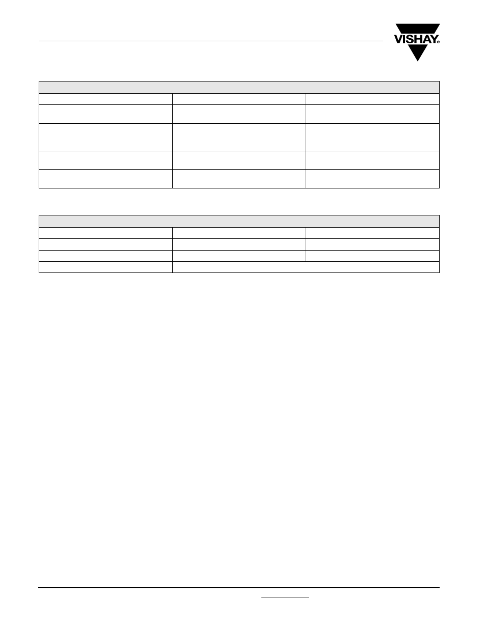
PERFORMANCE
TESTS
CONDITIONS
REQUIREMENTS
Momentary Overload
NF EN 140 000 CEI 115_1
4 Pr/10 s/
U
L
= 5000 V
< ± (0.25 % + 0.05
Ω)
Rapid Temperature Change
NF EN 140 000 CEI 68214 Test Na
5 cycles
- 55 °C + 125 °C
< ± (0.25 % + 0.05
Ω)
Load Life
NF EN 140 000 CEI 115_1
1000 h Pr at 70 °C
< ± (0.5 % + 0.05
Ω)
Humidity (steady state)
MIL STD 202 Method 103 B and D
56 days R.H. 95 %
< ± (0.5 % + 0.05
Ω)
RESISTANCE VALUE IN RELATION TO TOLERANCE AND TCR
Ohmic Value
< 1
Ω
> 1
Ω
Standard Tolerance
± 5 %
± 5 %
Standard TCR (- 55 °C to + 125 °C)
± 250 ppm/°C
± 150 ppm/°C
Tolerance On Request
± 1 % - ± 2 % - ± 10 %
P
ΔT
R
T H
j
c
–
(
) R
T H
c
a
–
(
)
+
[
]
---------------------------------------------------------------------
1
( )
=
ΔT
P
-------
75
180
----------