Adjustable wirewound enamelled resistors, Vishay sfernice – C&H Technology RA User Manual
Page 2
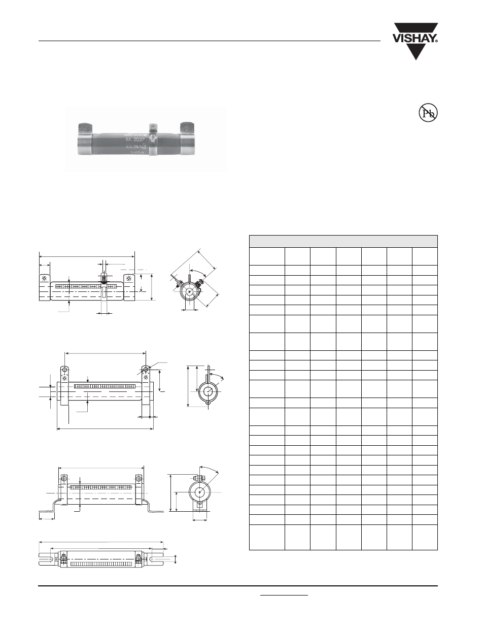
Adjustable Wirewound Enamelled Resistors
www.vishay.com
For technical questions, contact: [email protected]
Document Number: 50019
67
Revision: 21-Jun-06
RA
Vishay Sfernice
FEATURES
•
21 Watt to 180 Watt at 25°C
• NF C 93-214
- RBA 13 x 70
- RBA 20 x 117
- RBA 25 x 168
The ceramic tubular core ensures high dissipation capacity and excellent resistance to thermal shock and overload. The resistor
winding is evenly coiled on the core and protected by an enamel coating. A longitudinal opening provides for one or more
electrical connections by means of sliding collars equipped with a tongued connector.
DIMENSIONS in millimeters
* Also with CS and CR collars. See RW data sheet.
”B” Ring
WELDED STAINLESS STEEL 304 L BAND “B”
WELDED STAINLESS STEEL 304 L COLLAR “AN” TYPE 1
SCREWED STAINLESS STEEL 304 L “CS” TYPE 1
A
26
ØB
P
H
Q
45°
U
L
N
15
A
Ø4.2
F
ØB
E
D
O
ØC
J
K
45°
M
ØC
ØB
A
ØS
V
Z
T
X
R
45°
DIMENSIONS in millimeters
RA
MODEL
13 x 70
16 x 94
20 x 117 25 x 138 25 x 168 30 x 250
Connection
AN-B*
AN-B
AN-B
AN-B-CS AN-B-CS AN-B-CS
A ± 2
70
94
117
138
168
250
Ø B max.
16
19.5
23
28
28
33
Ø C min.
5
9
9
12
12
17
D
16 ± 0.5 17.5 ± 0.5 21 ± 0.7
23.5 ± 1
23.5 ± 1
26 ± 1
E +
0.5
+ 0
7
8
8
8
8
8
F +
0.5
+ 0
10.5
12
14
15
15
18
H ± 1
-
-
-
27
27
30
J max
19.5
23
25
27.5
27.5
30
K max
24
29.5
31.5
34
34
36.5
L -
0
- 4
-
-
-
199
229
317
M
56 ± 2
78 ± 2
98 ± 2
117 ± 2
147 ± 2
227 ± 2.5
N -
0
- 4
-
-
-
169
199
287
O max
24.5
28
33
38.5
38.5
43.5
P ± 1.5
–
–
–
50
50
60
Q ± 0.5
–
–
–
24
24
25
R
24 ± 0.5 26.5 ± 0.5 31 ± 0.7
33.5 ± 1
33.5 ± 1
36 ± 1
S
4.2
4.2
4.2
5.7
5.7
5.7
T
6.35
6.35
6.35
9
9
13
U ± 0.5
–
–
–
6.5
6.5
9
V
20 ± 0.5
21 ± 0.5
24 ± 0.7
28.5 ± 1
28.5 ± 1
33 ± 1
X
34.5 ± 1
38 ± 1
42 ± 1
51 ± 1.5
51 ± 1.5
55 ± 1.5
Z approx
3.5
5
6
6
6
5
Average
unit
weight in g
40
70
116
200
225
415