Datasheet, Vishay high power products, Rohs – C&H Technology GA200HS60S1PbF User Manual
Page 2
Document Number: 94362
For technical questions, contact: [email protected]
www.vishay.com
Revision: 29-Apr-08
1
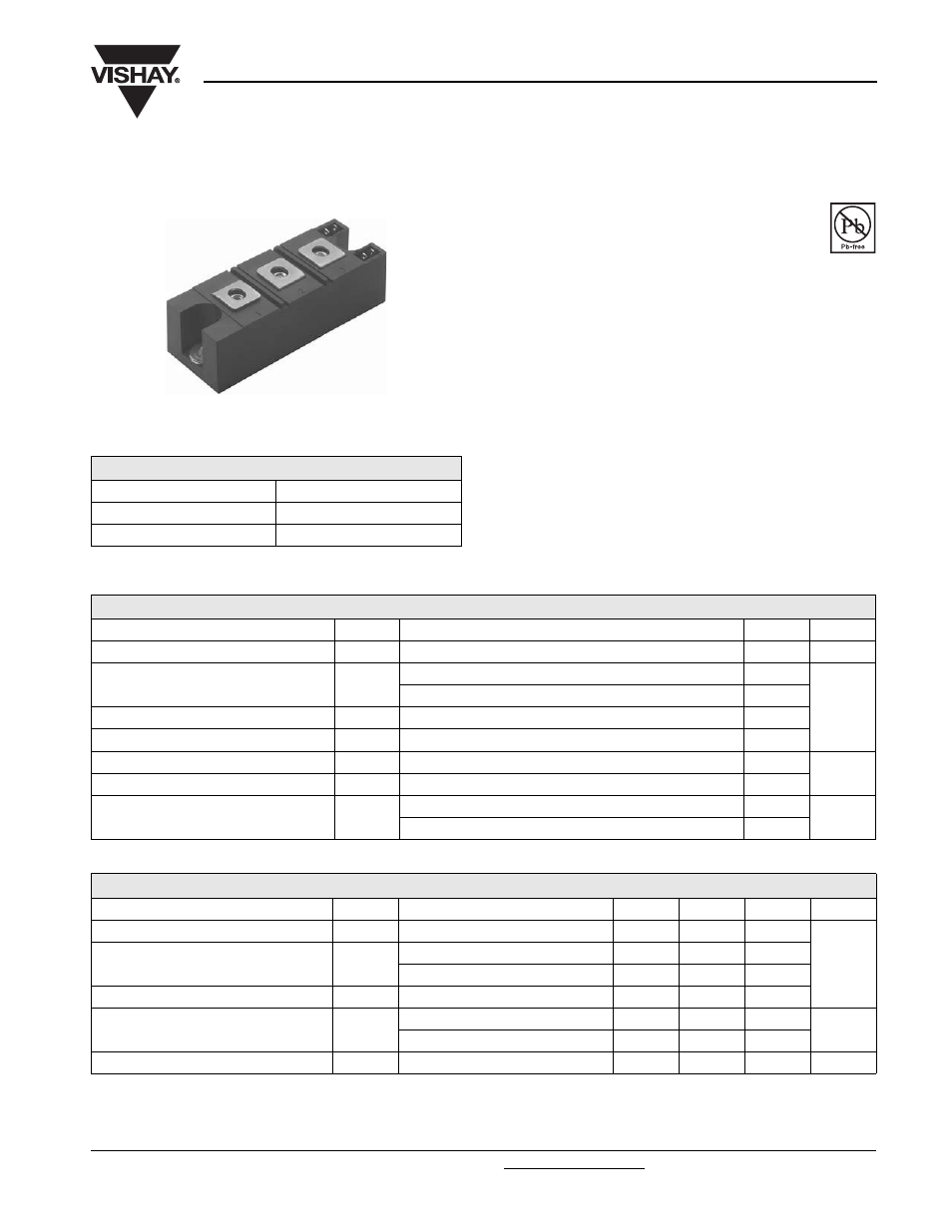
"Half-Bridge" IGBT INT-A-PAK
(Standard Speed IGBT), 200 A
GA200HS60S1PbF
Vishay High Power Products
FEATURES
• Generation 4 IGBT technology
• Standard speed: Optimized for hard switching
operating frequencies DC to 1 kHz
• Very low conduction losses
• Industry standard package
• Completely lead (Pb)-free
• Designed and qualified for industrial level
BENEFITS
• Increased operating efficiency
• Direct mounting to heatsink
• Performance optimized as output inverter stage for TIG
welding machines
PRODUCT SUMMARY
V
CES
600 V
I
C
DC
480 A
V
CE(on)
at 200 A, 25 °C
1.13 V
INT-A-PAK
RoHS
COMPLIANT
ABSOLUTE MAXIMUM RATINGS
PARAMETER SYMBOL
TEST
CONDITIONS
MAX.
UNITS
Collector to emitter voltage
V
CES
600
V
Continuous collector current
I
C
T
C
= 25 °C
480
A
T
C
= 116 °C
200
Pulsed collector current
I
CM
800
Peak switching current
I
LM
800
Gate to emitter voltage
V
GE
± 20
V
RMS isolation voltage
V
ISOL
Any terminal to case, t = 1 min
2500
Maximum power dissipation
P
D
T
C
= 25 °C
830
W
T
C
= 85 °C
430
ELECTRICAL SPECIFICATIONS (T
J
= 25 °C unless otherwise specified)
PARAMETER SYMBOL
TEST
CONDITIONS
MIN.
TYP.
MAX.
UNITS
Collector to emitter breakdown voltage
V
BR(CES)
V
GE
= 0 V, I
C
= 1 mA
600
-
-
V
Collector to emitter voltage
V
CE(on)
V
GE
= 15 V, I
C
= 200 A
-
1.13
1.21
V
GE
= 15 V, I
C
= 200 A, T
J
= 125 °C
-
1.08
1.18
Gate threshold voltage
V
GE(th)
I
C
= 0.25 mA
3
4.5
6
Collector to emitter leakage current
I
CES
V
GE
= 0 V, V
CE
= 600 V
-
0.025
1
mA
V
GE
= 0 V, V
CE
= 600 V, T
J
= 125 °C
-
-
10
Gate to emitter leakage current
I
GES
V
GE
= ± 20 V
-
-
± 250
nA