Vishay high power products, Power modules) – C&H Technology VSK.320 Series User Manual
Page 5
www.vishay.com
For technical questions, contact: [email protected]
Document Number: 93581
4
Revision: 22-Apr-08
VSK.250, .270, .320 Series
Vishay High Power Products
Standard Recovery Diodes, 250 to 320 A
(MAGN-A-PAK
TM
Power Modules)
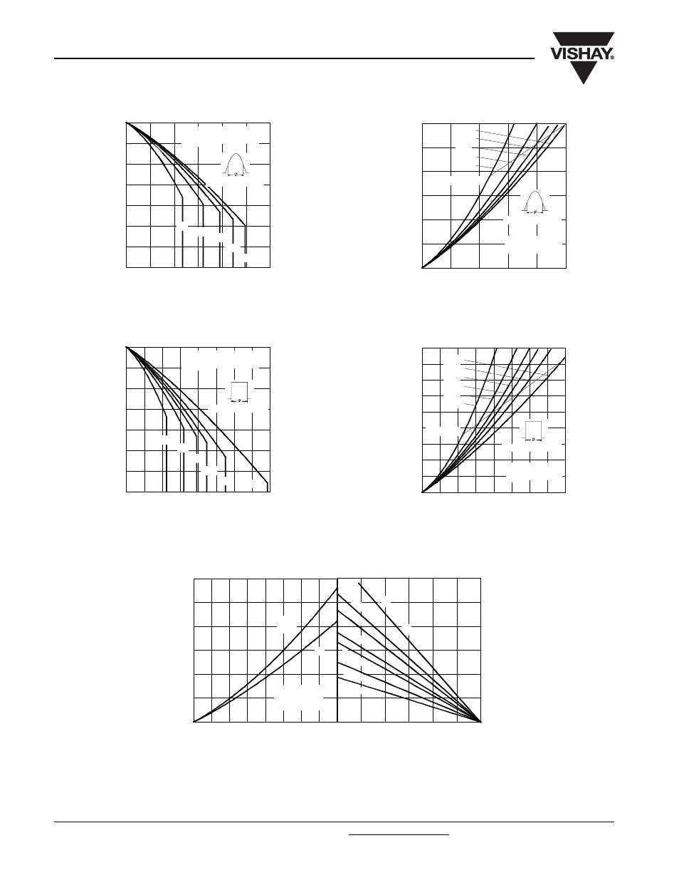
Fig. 1 - Current Ratings Characteristics
Fig. 2 - Current Ratings Characteristics
Fig. 3 - Forward Power Loss Characteristics
Fig. 4 - Forward Power Loss Characteristics
Fig. 5 - Forward Power Loss Characteristics
80
90
100
110
120
130
140
150
0
50
100
150
200
250
300
30°
60°
90°
120°
180°
M
a
x
imu
m
A
llo
w
a
b
le
C
a
se
T
e
mp
e
ra
tu
re
(
°C
)
Conduction Angle
Average Forward Current (A)
VSK.250.. Series
R (DC) = 0.16 K/ W
thJC
80
90
100
110
120
130
140
150
0
50
100 150 200 250 300 350 400
DC
30°
60°
90°
120°
180°
Ma
x
im
u
m
A
llo
w
a
b
le
C
a
se
T
e
m
p
e
ra
tu
re
(
°C
)
Conduction Period
Average Forward Current (A)
VSK.250.. Series
R (DC) = 0.16 K/ W
thJC
0
50
100
150
200
250
300
0
50
100
150
200
250
Average Forward Current (A)
RMS Limit
Ma
x
im
u
m
A
v
e
ra
g
e
F
o
rw
a
rd
P
o
w
e
r
Lo
ss
(
W
)
Conduc tion Angle
180°
120°
90°
60°
30°
VSK.250.. Series
T = 150°C
J
0
50
100
150
200
250
300
350
400
450
0
50
100 150 200 250 300 350 400
DC
180°
120°
90°
60°
30°
Average Forward Current (A)
RMS Limit
M
a
x
imu
m A
v
e
ra
g
e
F
o
rw
a
rd
P
o
w
e
r L
o
ss
(
W
)
Conduction Period
VSK.250.. Series
T = 150°C
J
0
25
50
75
100
125
150
Maximum Allowable Ambient Temperature (°C)
R
=
0
.0
2
K
/ W
-
D
e
lta
R
th
SA
0.0
8
K/
W
0.2
K/W
0.2
5 K
/ W
0.4 K
/ W
0.1
2
K/
W
0.6 K/ W
0
100
200
300
400
500
600
0
50
100 150 200 250 300 350 400
Total RMS Output Current (A)
Ma
x
im
u
m T
o
ta
l F
o
rw
a
rd
P
o
w
e
r L
o
ss
(
W
)
180°
(Sine)
DC
VSK.250.. Series
Per Junc tion
T = 150°C
J