St230spbf series, Vishay high power products, Phase control thyristors (stud version), 230 a – C&H Technology ST230SPbF Series User Manual
Page 5
www.vishay.com
For technical questions, contact: [email protected]
Document Number: 94399
4
Revision: 05-May-08
ST230SPbF Series
Vishay High Power Products
Phase Control Thyristors
(Stud Version), 230 A
• The table above shows the increment of thermal resistance R
thJC
when devices operate at different conduction angles than DC
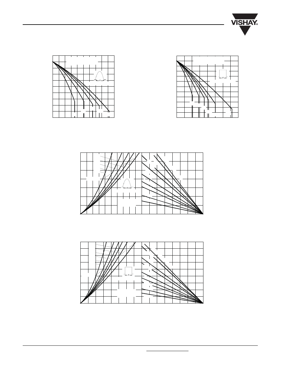
Fig. 1 - Current Ratings Characteristics
Fig. 2 - Current Ratings Characteristics
Fig. 3 - On-State Power Loss Characteristics
Fig. 4 - On-State Power Loss Characteristics
80
90
100
110
120
130
0
50
100
150
200
250
M
a
x
im
u
m
A
llo
w
a
bl
e
Cas
e
T
e
m
p
e
rat
u
re (
°C
)
30°
60°
90°
120°
180°
Average On-state Current (A)
Cond uc tion Angle
ST230S Series
R (DC) = 0.1 K/ W
thJC
70
80
90
100
110
120
130
0
100
200
300
400
DC
30°
60°
90°
120°
180°
Average On-state Current (A)
Ma
xi
m
u
m
Al
lo
w
a
b
le
C
a
se
T
e
m
p
e
ra
tu
re (
°C
)
Cond uc tion Period
ST230S Series
R (DC) = 0.1 K/ W
thJC
25
50
75
100
125
Maximum Allowable Ambient Temperature (°C)
R
=
0.0
8
K/
W
-
D
e
lta
R
th
SA
0.1
K/
W
0.1
6
K/
W
0.2
K/
W
0.3
K/W
0.4
K/ W
0.5
K/W
0.8 K
/ W
1.2 K/W
0
50
100
150
200
250
300
350
0
50
100
150
200
250
180°
120°
90°
60°
30°
RMS Limit
Conduction Angle
M
a
x
imu
m
A
v
e
rag
e O
n
-s
ta
te
P
o
wer
L
o
ss
(
W
)
Average On-state Current (A)
ST230S Series
T = 125°C
J
25
50
75
100
125
Maximum Allowable Ambient Temperature (°C)
R
=
0.08
K
/W
- D
e
lta
R
th
SA
0.1
K/
W
0.1
6
K/
W
0.2
K/ W
0.3
K/ W
0.4
K/ W
0.5 K
/ W
0.8 K/ W
1.2 K/ W
0
50
100
150
200
250
300
350
400
450
0
50
100 150 200 250 300 350 400
DC
180°
120°
90°
60°
30°
RMS Limit
Cond uc tion Period
M
a
x
imu
m A
v
e
ra
g
e
O
n
-s
ta
te
P
o
w
e
r L
o
ss
(
W
)
Average On-state Current (A)
ST230S Series
T = 125°C
J