C&H Technology PM25CLA120 User Manual
Page 4
3
PM25CLA120
Intellimod™ L-Series
Three Phase IGBT Inverter
25 Amperes/1200 Volts
Powerex, Inc., 200 E. Hillis Street, Youngwood, Pennsylvania 15697-1800 (724) 925-7272
Electrical and Mechanical Characteristics, T
j
= 25°C unless otherwise specified
Characteristics
Symbol
Test Conditions
Min.
Typ.
Max.
Units
IGBT Inverter Sector
Collector-Emitter Cutoff Current
I
CES
V
CE
= V
CES
, V
D
= 15V, T
j
= 25°C
—
—
1.0
mA
V
CE
= V
CES
, V
D
= 15V, T
j
= 125°C
—
—
10
mA
Diode Forward Voltage
V
EC
-I
C
= 25A, V
CIN
= 15V, V
D
= 15V
—
2.5
3.5
Volts
Collector-Emitter Saturation Voltage
V
CE(sat)
V
D
= 15V, V
CIN
= 0V, I
C
= 25A,
—
1.8
2.3
Volts
T
j
= 25°C
V
D
= 15V, V
CIN
= 0V, I
C
= 25A,
—
1.9
2.4
Volts
T
j
= 125°C
Inductive Load Switching Times
t
on
0.5
1.0
2.5
µs
t
rr
V
D
= 15V, V
CIN
= 0 ⇔ 15V
—
0.5
0.8
µs
t
C(on)
V
CC
= 600V, I
C
= 25A
—
0.4
1.0
µs
t
off
T
j
= 125°C
—
2.0
3.0
µs
t
C(off)
—
0.7
1.2
µs
Control Sector
Short Circuit Trip Level
SC
-20°C ≤ T
j
≤ 125°C, V
D
= 15V
50
—
—
Amperes
Short Circuit Current Delay Time
t
off(SC)
V
D
= 15V
—
0.2
—
µs
Over Temperature Protection
OT
Trip Level
135
145
155
°C
(Detect T
j
of IGBT Chip)
OT
R
Reset Level
—
125
—
°C
Supply Circuit Under-voltage Protection
UV
Trip Level
11.5
12.0
12.5
Volts
(-20 ≤ T
j
≤ 125°C)
UV
R
Reset Level
—
12.5
—
Volts
Circuit Current
I
D
V
D
= 15V, V
CIN
= 15V, V
N1
-V
NC
—
15
25
mA
V
D
= 15V, V
CIN
= 15V, V
XP1
-V
XPC
—
5
10
mA
Input ON Threshold Voltage
V
th(on)
Applied between U
P
-V
UPC
,
1.2
1.5
1.8
Volts
Input OFF Threshold Voltage
V
th(off)
V
P
-V
VPC
, W
P
-V
WPC
, U
N
- V
N
- W
N
-V
NC
1.7
2.0
2.3
Volts
Fault Output Current*
I
FO(H)
V
D
= 15V, V
CIN
= 15V
—
—
0.01
mA
I
FO(L)
V
D
= 15V, V
CIN
= 15V
—
10
15
mA
Fault Output Pulse Width*
t
FO
V
D
= 15V
1.0
1.8
—
ms
*Fault output is given only when the internal SC, OT and UV protections schemes of either upper or lower devide operate to protect it.
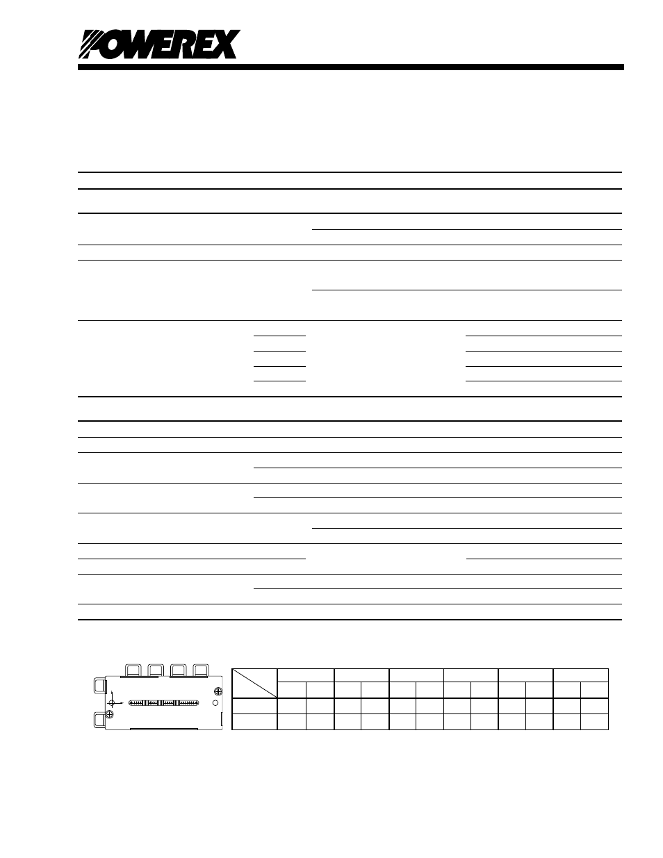
Arm
UP
VP
WP
UN
VN
WN
Axis
IGBT FWDi IGBT FWDi IGBT FWDi IGBT FWDi IGBT FWDi IGBT FWDi
X
29.0 29.3 64.0 65.5 85.6 85.9 37.8 37.5 55.2 55.7 75.8 75.3
Y
-7.1
1.5
-7.1
2.0
-7.1
2.0
5.1
-4.5
5.1
-4.5
5.1
-4.5
T
C
Measurement Point
Y
BOTTOM VIEW
X