Sd400n/r series, Vishay high power products, Standard recovery diodes (stud version), 400 a – C&H Technology SD400N-R Series User Manual
Page 4: Conduction
Document Number: 93548
For technical questions, contact: [email protected]
www.vishay.com
Revision: 17-Apr-08
3
SD400N/R Series
Standard Recovery Diodes
(Stud Version), 400 A
Vishay High Power Products
Note
• The table above shows the increment of thermal resistance R
thJC
when devices operate at different conduction angles than DC
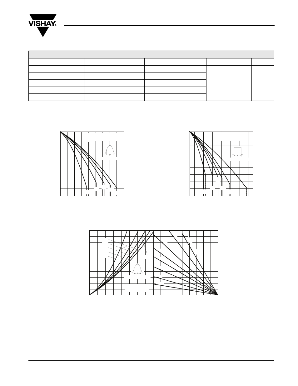
Fig. 1 - Current Ratings Characteristics
Fig. 2 - Current Ratings Characteristics
Fig. 3 - Forward Power Loss Characteristics
ΔR
thJC
CONDUCTION
CONDUCTION ANGLE
SINUSOIDAL CONDUCTION
RECTANGULAR CONDUCTION
TEST CONDITIONS
UNITS
180°
0.020
0.013
T
J
= T
J
maximum
K/W
120°
0.023
0.023
90°
0.029
0.031
60°
0.042
0.044
30°
0.073
0.074
110
120
130
140
150
160
170
180
190
0
50 100 150 200 250 300 350 400 450
30°
60°
90°
120°
180°
Average Forward Current (A)
Conduction Angle
M
a
x
im
u
m Al
lo
w
a
b
le
Ca
se
T
e
mp
e
ra
tu
re
(
°C)
SD400N/ R Series
R (DC) = 0.11 K/ W
thJC
100
110
120
130
140
150
160
170
180
190
0
100
200
300
400
500
600
700
DC
30°
60°
90°
120°
180°
Conduction Period
M
a
xi
mu
m A
llo
w
a
b
le
Ca
se
T
e
mp
e
ra
tu
re
(
°C)
Average Forward Current (A)
SD400N/ R Series
R (DC) = 0.11 K/ W
thJC
10
30
50
70
90 110 130 150 170 190
Maximum Allowable Ambient Temperature (°C)
0.2
K/
W
0.3
K/W
0.4
K/ W
0.6
K/ W
1 K/ W
R
=
0
.0
4
K
/W
-
D
e
lta
R
th
SA
0.1
K/
W
1.8 K/ W
0
50
100
150
200
250
300
350
400
450
500
550
0
50
100 150 200 250 300 350 400
180°
120°
90°
60°
30°
RMS Limit
Cond uc tion Angle
M
a
x
im
u
m
A
v
er
a
g
e
F
o
rw
ar
d P
o
w
e
r L
o
ss
(
W
)
Average Forward Current (A)
SD400N/ R Series
T = 190°C
J