Mbr10.. series, Vishay high power products, Schottky rectifier, 10 a – C&H Technology MBR10.. Series User Manual
Page 4
Document Number: 93437
For technical questions, contact: [email protected]
www.vishay.com
Revision: 22-Aug-08
3
MBR10.. Series
Schottky Rectifier, 10 A
Vishay High Power Products
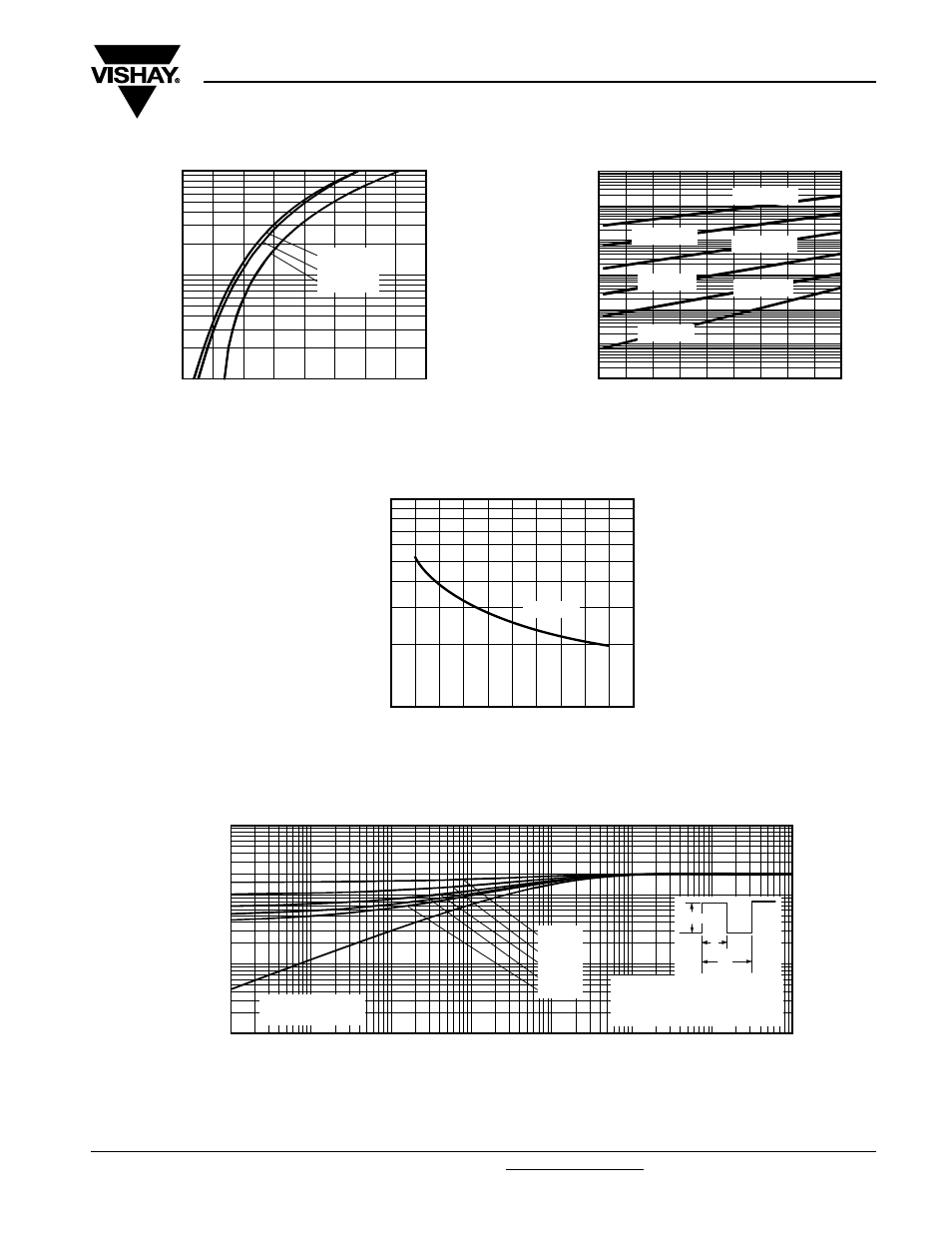
Fig. 1 - Maximum Forward Voltage Drop Characteristics
Fig. 2 - Typical Values of Reverse Current vs.
Reverse Voltage
Fig. 3 - Typical Junction Capacitance vs. Reverse Voltage
Fig. 4 - Maximum Thermal Impedance Z
thJC
Characteristics
V
FM
- Forward Voltage Drop (V)
I
F
- Instantaneous Forward Current (A)
1.4
0.2
0.4
0.6
0.8
1.0
1.2
1.6
1
10
100
1.8
T
J
= 150 °C
T
J
= 125 °C
T
J
= 25 °C
V
R
- Reverse Voltage (V)
I
R
- Reverse Current (mA)
0.0001
0.001
0.01
0.1
1
0
20
25
35
45
10
100
T
J
= 150 °C
T
J
= 125 °C
T
J
= 100 °C
T
J
= 75 °C
T
J
= 50 °C
T
J
= 25 °C
5
10
15
30
40
1000
V
R
- Reverse Voltage (V)
C
T
- Junction Capacitance (pF)
0
100
10
30
40
20
50
T
J
= 25 °C
t
1
- Rectangular Pulse Duration (s)
Z
thJC
- Thermal Impedance (°C/W)
0.1
1
10
0.00001
0.0001
0.001
0.01
100
.
P
DM
t
1
t
2
Notes:
1. Duty factor D = t
1
/t
2
2. Peak T
J
= P
DM
x Z
thJC
+ T
C
Single pulse
(thermal resistance)
D = 0.75
D = 0.33
D = 0.25
D = 0.20
D = 0.50
0.01
0.1
1.0
10