Datasheet, Power resistors, thick film technology, Rto 20 – C&H Technology RTO20 User Manual
Page 2: Vishay sfernice
Power Resistors, Thick Film Technology
www.vishay.com
For technical questions, contact: [email protected]
Document Number: 50005
14
Revision: 24-Nov-08
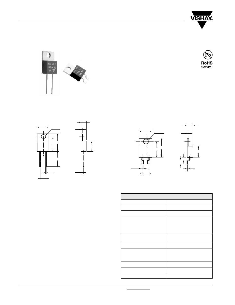
RTO 20
Vishay Sfernice
The well known TO 220 package is compact and easy to
mount.
FEATURES
• 20 W at 25 °C heatsink mounted
• High power dissipation to size ratio
• Wide resistance range from 0.01 Ω to 550 kΩ
• Negligible inductance
• Easy mounting
• TO 220 package: Compact and easy to mount
Two versions of this thick film resistor are available:
• A radial leaded version for PCB mounting
• A flat lead version for surface mounting
DIMENSIONS in millimeters
MECHANICAL SPECIFICATIONS
Mechanical Protection
Insulated case
Resistive Element Thick
Film
Connections Tinned
copper
Weight
2.2 g max.
DIMENSIONS
Standard Package TO
220
Insulated case
ENVIRONMENTAL SPECIFICATIONS
Temperature Range
- 55 °C to + 155 °C
Climatic Category
55/155/56
Sealing Sealed
container
Solder immersion
Flammability IEC
60695-11-5
2 applications 30 s seperated
by 60 s
• Tolerance unless otherwise specified: ± 0.4 mm
RTO 20F - LEADED
4.5
1.3
8.8
Ш 0.8
10.1
13.7
12.5
5.08
15
Ш 3.6
2.5
RTO 20C - FOR SURFACE MOUNTING
4.5
1.3
8.8
10.1
12.5
5.08
15
Ø 3.6
0.3
1.6
3
2
• Only for RTO 20 version C = during surface mount soldering temperature profile
must not cause the metal tab of this device to exceed 220 °C.
ELECTRICAL SPECIFICATIONS
Resistance Range
0.010
Ω to 550 kΩ serie E24
Tolerances (Standard)
± 1 % to ± 10 %
Dissipation and Associated:
Onto a heatsink
Thermal Resistance
and Nominal Power
20 W at + 25 °C
R
TH (j - c)
: 6.5 °C/W
free air:
2 W at + 25 °C
Temperature Coefficient
Standard (- 55 °C; + 150 °C)
See Performance table
± 150 ppm/°C
Limiting Element Voltage U
L
250 V
Dielectric Strength
MIL STD 202
2000 V
RMS
- 1 min - 10 mA max.
(between terminals
and heatsink)
Insulation Resistance
≥ 10
6
M
Ω
Inductance
≤ 0.1 µH
Critical Resistance
3.12 k
Ω