Lps 1100, Vishay sfernice – C&H Technology LPS1100 User Manual
Page 4
LPS 1100
www.vishay.com
Vishay Sfernice
Revision: 14-Jun-12
3
Document Number: 50059
For technical questions, contact:
THIS DOCUMENT IS SUBJECT TO CHANGE WITHOUT NOTICE. THE PRODUCTS DESCRIBED HEREIN AND THIS DOCUMENT
ARE SUBJECT TO SPECIFIC DISCLAIMERS, SET FORTH AT
www.vishay.com/doc?91000
Note
• Configuration 1: Water cooling heatsink (CP15 from Lytron (304 mm x 95.3 mm x 8 mm) with water flow rate 4LPM and thermal grease Si340
from BlueStar Silicones
Configuration 2: Air cooling heatsink P207/250 from Semikron (250 mm x 200 mm x 72 mm) and thermal grease Si340 from BlueStar
Silicones
Configuration 3: Water cooling heatsink (CP15 from Lytron (304 mm x 95.3 mm x 8 mm) with water flow rate 4LPM and thermal pad
Q-pad II from Berquist
Configuration 4: Air cooling heatsink P207/250 from Semikron (250 mm x 200 mm x 72 mm) and thermal pad Q-pad II from Berquist
OVERLOAD
In any case the applied voltage must be lower than
U
I
= 6600 V.
Short time overload: 2 x Pr/10 s for heatsink with
R
th(h-a)
0.26 °C/W (maximum power: 700 W) and 1.6 x
Pr/1 s for heatsink with 0.26 °C/W > R
th(h-a)
0.059 °C/W
(maximum power: 1800 W).
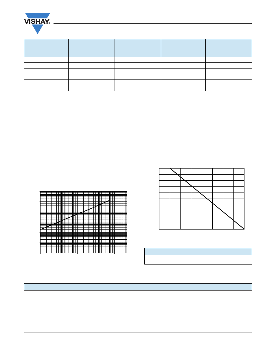
Accidental overload: The values indicated on the following
graph are applicable to resistors in air or mounted onto a
heatsink.
ENERGY CURVE
MARKING
Series, style, ohmic value (in
), tolerance (in %),
manufacturing date, Vishay Sfernice trademark.
POWER RATING
The temperature of the case should be maintained within
the limit specified in the following figure. To optimize
the thermal conduction, contacting surfaces should be
coated with silicone grease or thermal film, and heatsink
mounting screws tightened to 2 Nm.
CONFIG. 1:
WATER COOLING
HEATSINK CP15 AND
THERMAL GREASE SI340
CONFIG. 2:
AIR COOLING
HEATSINK P207/250 AND
THERMAL GREASE SI340
CONFIG. 3:
WATER COOLING
HEATSINK CP15 AND
THERMAL PAD Q-PAD II
CONFIG. 4:
AIR COOLING
HEATSINK P207/250 AND
THERMAL PAD Q-PAD II
Power Dissipation (W)
1100
350
650
285
T° Resistive Element (°C)
200
200
200
200
R
th(j-c)
max. (°C/W)
0.039
0.039
0.039
0.039
R
th(c-h)
typ. (°C/W)
0.070
0.201
0.187
0.315
R
th(h-a)
max. (°C/W)
0.059
0.260
0.059
0.260
Fluid T° (°C)
15 (water)
25 (air)
15 (water)
25 (air)
ENERGY IN J
0.01
0.1
1
10
100
10 000
OVERLOAD DURATION IN s
1
10
-7
10
-6
10
-5
10
-4
10
-3
10
-2
10
-1
1000
PACKAGING
Box of 15 units
0
20
40
60
80
100
RA
TED PO
WER IN %
HEATSINK TEMPERATURE IN °C
200
0
175
150
125
100
75
50
25
ORDERING INFORMATION
LPS
1100
1 k
± 1 %
xxx
BO15
e
MODEL
STYLE
RESISTANCE
VALUE
TOLERANCE
CUSTOM
DESIGN
PACKAGING
LEAD (Pb)-FREE
± 1 %
± 2 %
± 5 %
± 10 %
Optional on
request:
special TCR,
shape, etc.