3 function chart – VEGA VEGASWING 66 - Relay User Manual
Page 21
21
6 Setup
VEGASWING 66 • - Relay
43756-EN-130322
•
Red LED lights = fault
•
Relay deenergizes
The signal lamp for indication of the switching condition of the relay.
With the mode adjustment (4), the switching condition and hence the
function of the signal lamp can be changed.
•
Yellow LED lights = relay energized
•
Green LED lights = operating voltage on
With the mode adjustment (min./max.) you can change the switching
condition of the relay. You can set the required mode according to the
"Function chart" (max. - max. detection or overflow protection, min. -
min. detection or dry run protection).
With this DIL switch (3) you can set the switching point to liquids
having a density between 0.5 and 0.7 g/cm³ (0.018 and 0.025 lbs/
in³). With the basic setting, liquids with a density of ≥ 0.7 g/cm³ (0.025
lbs/in³) can be detected. In liquids with lower density, you must set
the switch to ≥ 0.5 g/cm³ (0.018 lbs/in³). The specifications for the
position of the switching point relate to water - density value 1 g/cm³
(0.036 lbs/in³). In products with a different density, the switching point
will shift in the direction of the housing or tuning fork end depending
on the density and type of installation.
Note:
Keep in mind that foams with a density > 0.45 g/cm³ (0.016 lbs/in³)
are detected by the sensor. This can cause faulty switchings particu-
lary when used as dry run protection system.
Note:
In case of strong boiling or deployment processes as well as extreme
outgasing, the density of the gas/product mixture on the product
surface can be so low that it can be no longer detected by the sensor.
This can cause faulty switchings.
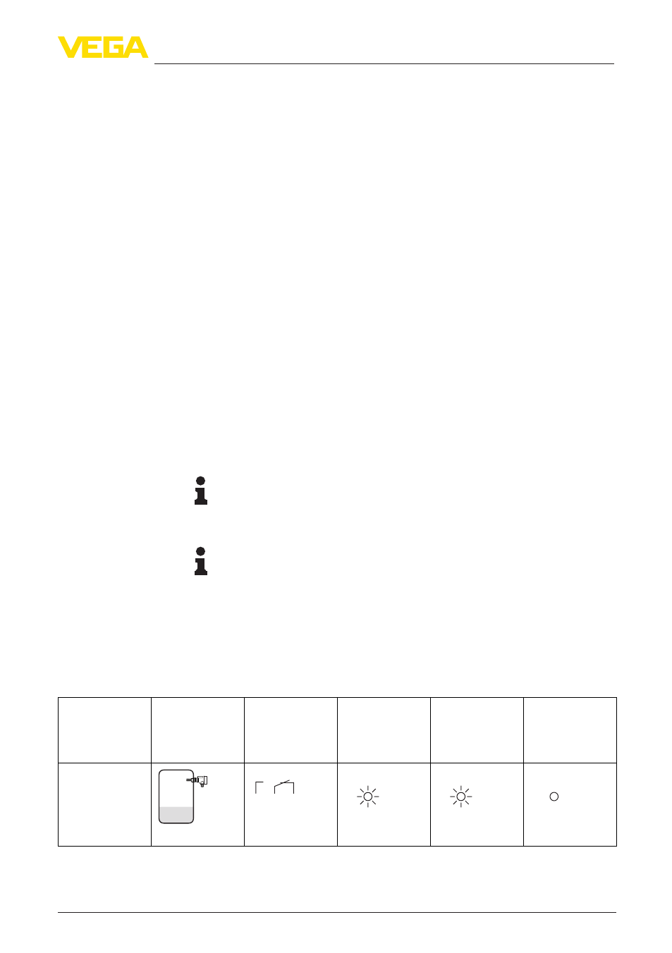
6.3 Function chart
The following chart provides an overview of the switching conditions
depending on the set mode and the level.
Level
Switching sta-
tus
Signal lamp -
green
Voltage supply
Signal lamp -
yellow
Switching sta-
tus
Signal lamp
- red
Fault message
Mode max.
Overflow pro-
tection
5
3
4
(8)
(6) (7)
Relay energized
Signal lamp (2) - Switch-
ing condition (yellow)
Signal lamp (3) - Operat-
ing condition (green)
Mode adjustment (4)
Sensitivity adjustment (5)