VEGA VEGAPULS 62 (≥ 2.0.0 - ≥ 4.0.0) 4 … 20 mA_HART - two-wire User Manual
Page 25
25
4 Mounting
VEGAPULS 62 • 4 … 20 mA/HART - two-wire
36503-EN-121011
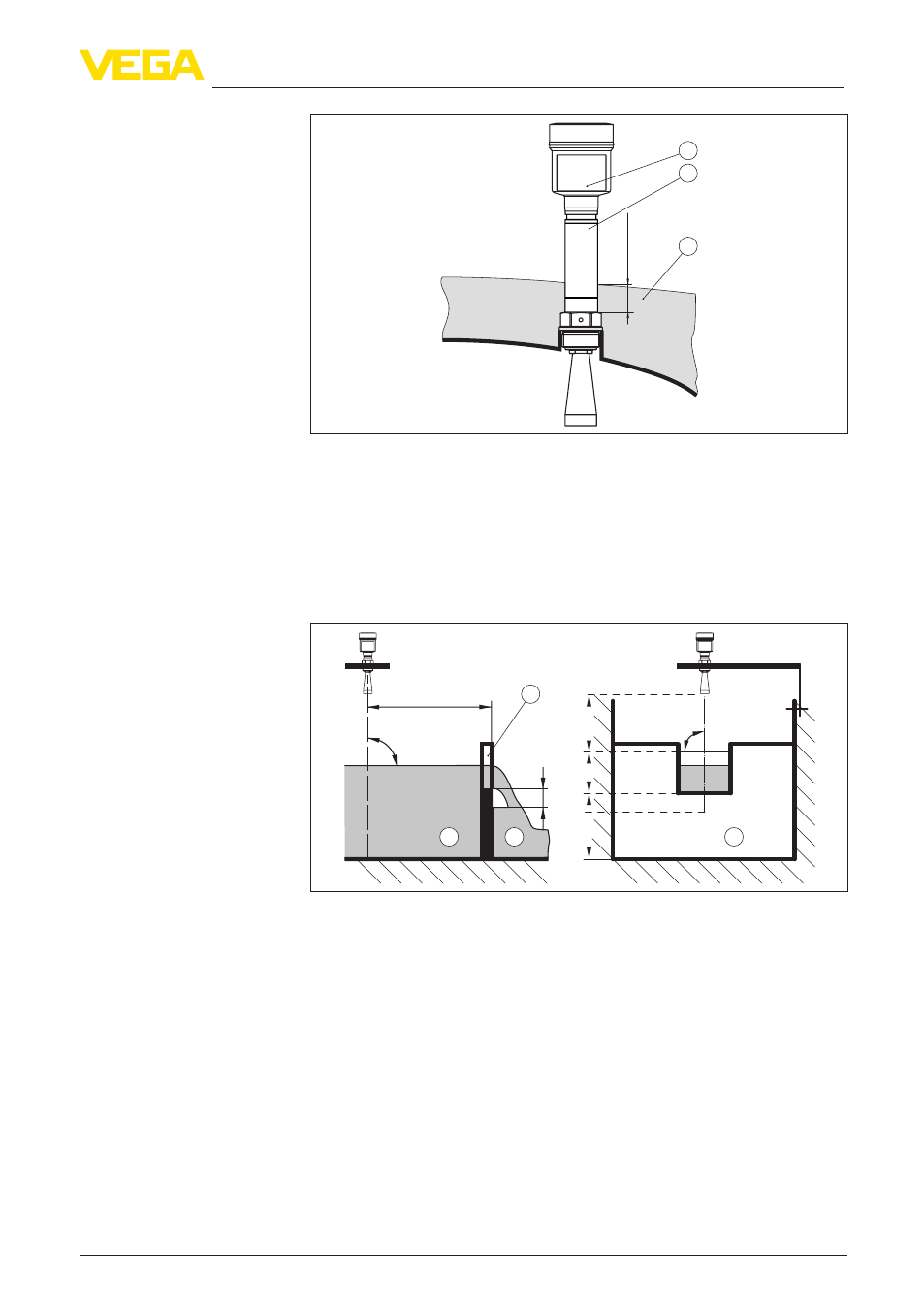
max. 50 mm (1.97"
)
1
2
3
Fig. 21: Mounting of the instrument with insulated vessels.
1 Electronics housing
2 Distance piece
3 Vessel insulation
The short examples give you introductory information on the flow
measurement. Detailed planning information is available from flume
manufacturers and in special literature.
3 ... 4 h
max
≥ 50 mm
90°
2
3
1
h
ma
x
d
mi
n
≥ 2 mm x
h
ma
x
90°
4
2
3
Fig. 22: Flow measurement with rectangular flume: d
min.
= min. distance of the
sensor (see chapter "Technical data"); h
max.
= max. filling of the rectangular
flume
1 Overflow orifice (side view)
2 Headwater
3 Tail water
4 Overfall orifice (view from bottom water)
In general, the following points must be observed:
•
Install the sensor on the headwater side
•
Installation in the centre of the flume and vertical to the liquid
surface
•
Distance to the overfall orifice
•
Distance of orifice opening above ground
•
Min. distance of the orifice opening to bottom water
•
Min. distance of the sensor to max. storage level
Flow measurement with
rectangular flume