4 assembly steps, two-part antenna extension, 5 mounting control – VEGA VEGAPULS 68 Antenna extension up to 450 °C User Manual
Page 9
9
3 Mounting
Antenna extension up to 450 °C • for VEGAPULS 62 and 68
38316-EN-131119
2. Turn bent (angled) antenna extensions in such a way that the
bending axis is exactly parallel to the polarisation marking and
the optional rinsing air connection matches with the polarisation
marking.
3. Make sure that antenna extension and radar sensor are assem-
bled gap free
4. Tighten screws crosswise, torque max. 2.0 Nm (1.844 lbf ft)
Assembly is finished.
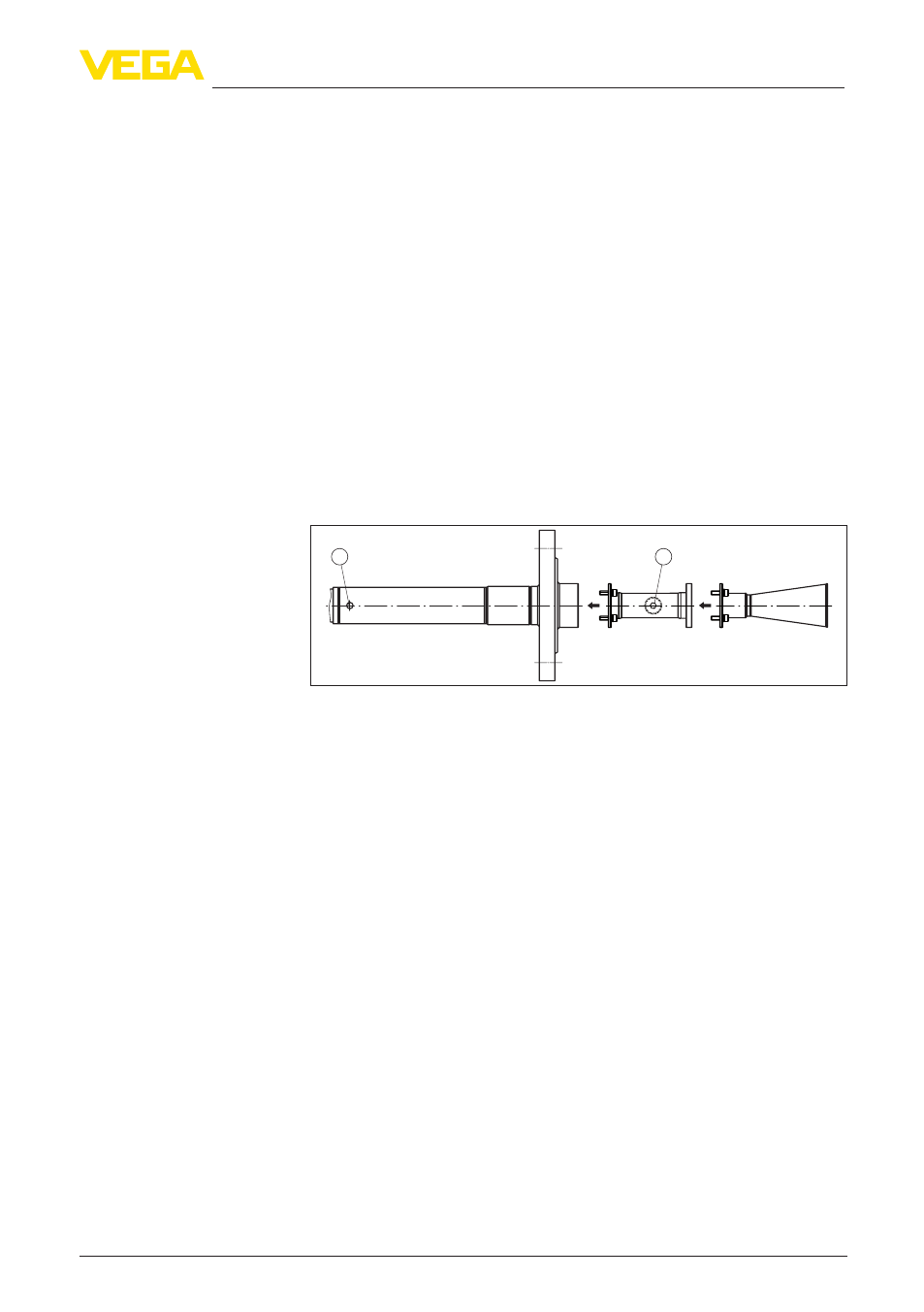
3.4 Assembly steps, two-part antenna extension
With multi-sectional antenna extensions, the antenna system consists
of upper part and antenna. The parts are shipped disassembled and
must be reassembled on site.
Proceed as follows:
1. Remove the protection cap from the horn antenna
2. Assemble the radar sensor and the individual parts of the an-
tenna extension
1
2
Fig. 7: Assembly of two-part antenna extension
1 Marking for polarisation
2 Rinsing air connection
3. Fasten the individual parts with the supplied screws, starting with
the antenna and ending with the upper part
4. Turn the antenna extension in such a way that the optional rinsing
air connection corresponds to the polarisation marking.
5. Make sure that all parts are assembled gap free
6. Tighten screws crosswise, torque max. 2.0 Nm (1.844 lbf ft)
Assembly is finished.
3.5 Mounting control
Angled, multi-sectional or incorrectly mounted antenna extensions in
particular can cause false echoes at close range. These false echoes
can influence the function of the measurement. When retrofitting an
antenna extension, we recommend making sure all components are
correctly mounted before setting up the measurement. Therefore,
check sensor and antenna extension for gaps and non-aligned polari-
sation markings and correct if necessary.