3 mounting, 1 mounting preparations, 2 mounting instructions – VEGA VEGAPULS 68 Antenna extension up to 450 °C User Manual
Page 7
7
3 Mounting
Antenna extension up to 450 °C • for VEGAPULS 62 and 68
38316-EN-131119
3 Mounting
3.1 Mounting preparations
When the antenna extension is shipped with the radar sensor, calibra-
tion is carried out beforehand in the factory. The radar sensor is thus
adapted to the antenna extension. To ensure correct functioning of the
measurement, an unambiguous allocation of the antenna extension to
the radar sensor is necessary. For this purpose the antenna parts are
marked with the serial number of the sensor.
Note:
An incorrect combination will compromise the accuracy. Make sure
that sensor and antenna extension belong together.
Electromagnetic radar signals are polarized, i.e. aligned with a certain
plane. With an angled antenna extension as well as versions with
rinsing air connection, the bending axis must be aligned with this po-
larisation. The procedure is described in chapters "Assembly steps".
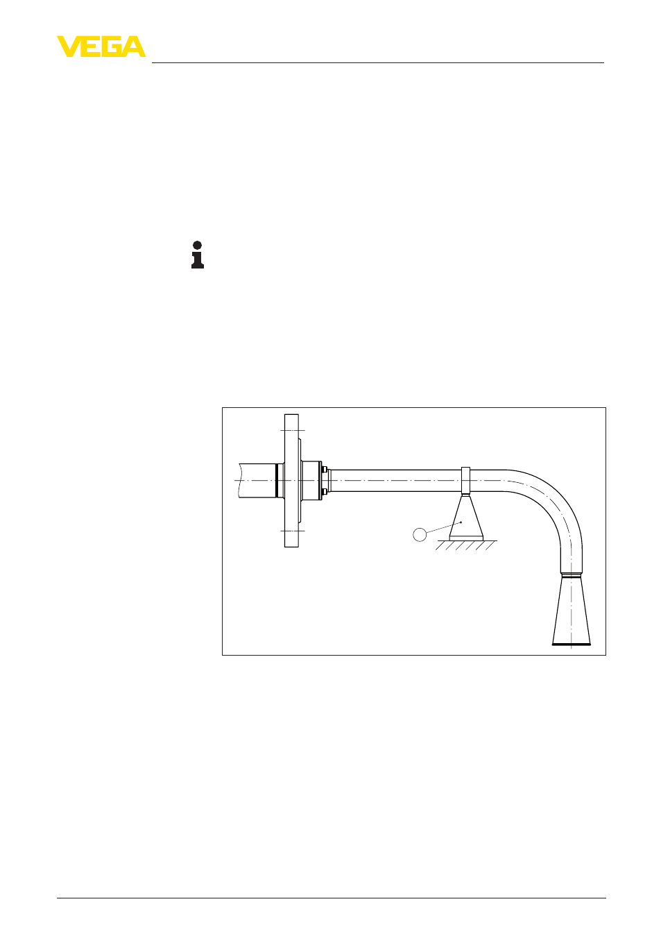
In case of very long antenna extensions or heavy mechanical loads,
some kind of support is required.
1
Fig. 4: Absorption of mechanical loads by supports
1 Support
The following tools are required for mounting:
•
Hexagon socket wrench, size 4
3.2 Mounting instructions
Antenna extensions must be mounted not only with mechanical but
also microwave-specific considerations in mind. To ensure reliable
functioning of the sensors, gap-free mounting of the antenna exten-
sion sections in the correct position is necessary.
Assignment
Polarisation
Support
Tools
Gap-free mounting