6 examples of telegram configuration, 7 data format of the output signal – VEGA VEGAPULS 66 (≥ 2.0.0 - ≥ 4.0.0) standpipe ver. Profibus PA User Manual
Page 54
54
11 Supplement
VEGAPULS 66 standpipe version • Profibus PA
36525-EN-121011
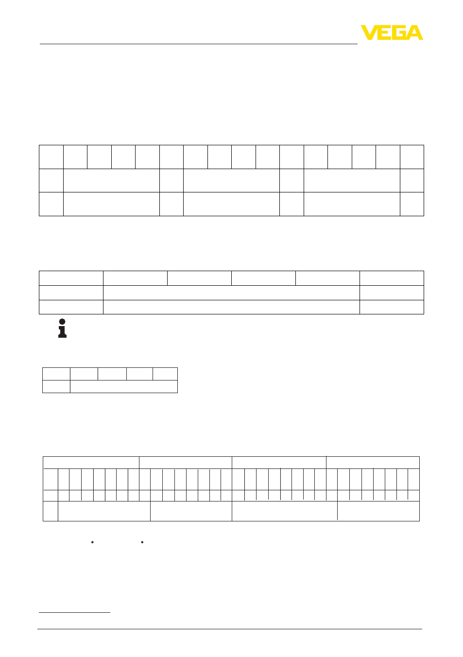
11.6 Examples of telegram configuration
In the following you will see how the modules can be combined and how the appendant data tel-
egram is structured.
Example 1
•
AI FB1 (OUT)
•
AI FB2 (OUT)
•
AI FB3 (OUT))
Byte-
No.
1
2
3
4
5
6
7
8
9
10
11
12
13
14
15
For-
mat
IEEE-754-Floating point
value
Sta-
tus
IEEE-754-Floating point
value
Sta-
tus
IEEE-754-Floating point
value
Sta-
tus
Value
AI FB1 (OUT)
AI
FB1
AI FB2 (OUT)
AI
FB2
AI FB3 (OUT)
AI
FB3
Example 2
•
AI FB1 (OUT)
•
Free Place
•
Free Place
Byte-No.
1
2
3
4
5
Format
IEEE-754-Floating point value
Status
Value
AI FB1 (OUT)
AI FB1
Note:
Bytes 6-15 are not used in this example.
11.7 Data format of the output signal
Byte4 Byte3 Byte2 Byte1 Byte0
Status
Value (IEEE-754)
Fig. 30: Data format of the output signal
The status byte corresponds to profile 3.02 "Profibus PA Profile for Process Control Devices" coded.
The status "Measured value OK" is coded as 80 (hex) (Bit7 = 1, Bit6 … 0 = 0).
The measured value is transferred as a 32 bit floating point number in the IEEE-754 format.
Byte n
Byte n+1
Bit
7
VZ
Exponent
Bit
6
2
Bit
5
2
Bit
4
2
Bit
3
2
Bit
2
2
Bit
1
2
Bit
0
2
Bit
7
2
Bit
6
2
Bit
5
2
Bit
4
2
Bit
3
2
Bit
2
2
Bit
1
2
Bit
0
2
Sign
Bit
Significant
7
6
5
4
3
2
1
0
-1
-2
-3
-4
-5
-6
-7
Byte n+2
Byte n+3
Bit
7
2
Significant
Bit
6
2
Bit
5
2
Bit
4
2
Bit
3
2
Bit
2
2
Bit
1
2
Bit
0
2
Bit
7
2
Bit
6
2
Bit
5
2
Bit
4
2
Bit
3
2
Bit
2
2
Bit
1
2
Bit
0
2
Significant
-9
-10 -11 -12 -13 -14 -15 -16 -17 -18 -19 -20 -21 -22 -23
-8
Value = (-1)
VZ
2
(Exponent - 127)
(1 + Significant)
Fig. 31: Data format of the measured value
11.8 Coding of the status byte associated with the PA output value
You can find further information for the coding of the status byte in the Device Description 3.02 on
www.profibus.com.