5 connecting to power supply, 1 preparing the connection, 2 wiring plan – VEGA EL 1 Conductive probe User Manual
Page 12: 5connecting to power supply
5
Connecting to power supply
5
.1 Preparing the connection
Always keep in mind the following safety instructions:
l
Connect only in the complete absence of line voltage
You can find the electrical connection of EL 1 in the operating
instructions manual of the corresponding signal conditioning instru-
ment.
You can find suitable signal conditioning instruments in chapter
"T
echnical data".
The instrument is connected with standard two-wire cable without
screen. If electromagnetic interference is expected which is above the
test values of EN 61326 for industrial areas, screened cable should be
used.
Use cable with round cross-section. A cable outer diameter of 5 … 9 mm
(0.2 … 0.35 in) ensures the seal effect of the cable gland. If you are
using cable with a different diameter or cross-section, exchange the
seal or use a suitable cable gland.
5
.2 Wiring plan
You can find the electrical connection of EL 1 in the operating
instructions manual of the corresponding signal conditioning instru-
ment.
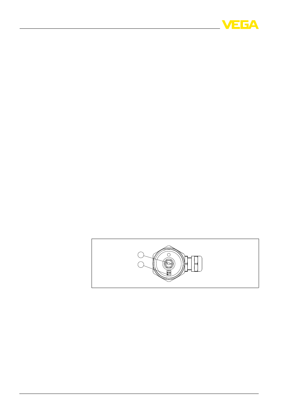
1
2
Fig. 5: Connection compartment
1
Mass
2
Max.
The line break monitoring or alarm function defines the function of the
signal conditioning instrument in case of failure.
To realize line monitoring with a signal conditioning instrument
VEGATOR 632, an additional component must be mounted in the
connection housing of the probe.
Note safety instructions
Power supply
Connection cable
Connection compart-
ment
Line monitoring with
VEGATOR 632
12
Conductive probe EL 1
5 Connecting to power supply
32651
-EN
-100208