3 function chart – VEGA VEGAWAVE 61 - Relay (DPDT) User Manual
Page 19
By default, the potentiometer of VEGAWAVE 61 is set to the right stop
(> 0.02 g/cm³ or 0.0008 lbs/in³). In case of very light-weight solids, turn
the potentiometer to the left stop (> 0.008 g/cm³ or 0.0003 lbs/in³).
VEGAWAVE
61 will thus be more sensitive and can detect light-weight
solids more reliably.
For instruments detecting solids in water, these settings are not
applicable. The switching point adaptation is preset and must not be
changed.
With the mode adjustment (min./max.) you can change the switching
condition of the relay. You can set the required mode according to the
"F
unction chart" (max. - max. detection or overflow protection, min. -
min. detection or dry run protection).
We recommend connecting according to the quiescent current
principle (relay contact deenergizes when the switching point is
reached), because the relay always takes on the same (safe) condition
if a failure is detected.
Control lamp for indication of the switching status
l
green = relay energized
l
red = relay deenergized
l
red (flashing) = failure
6
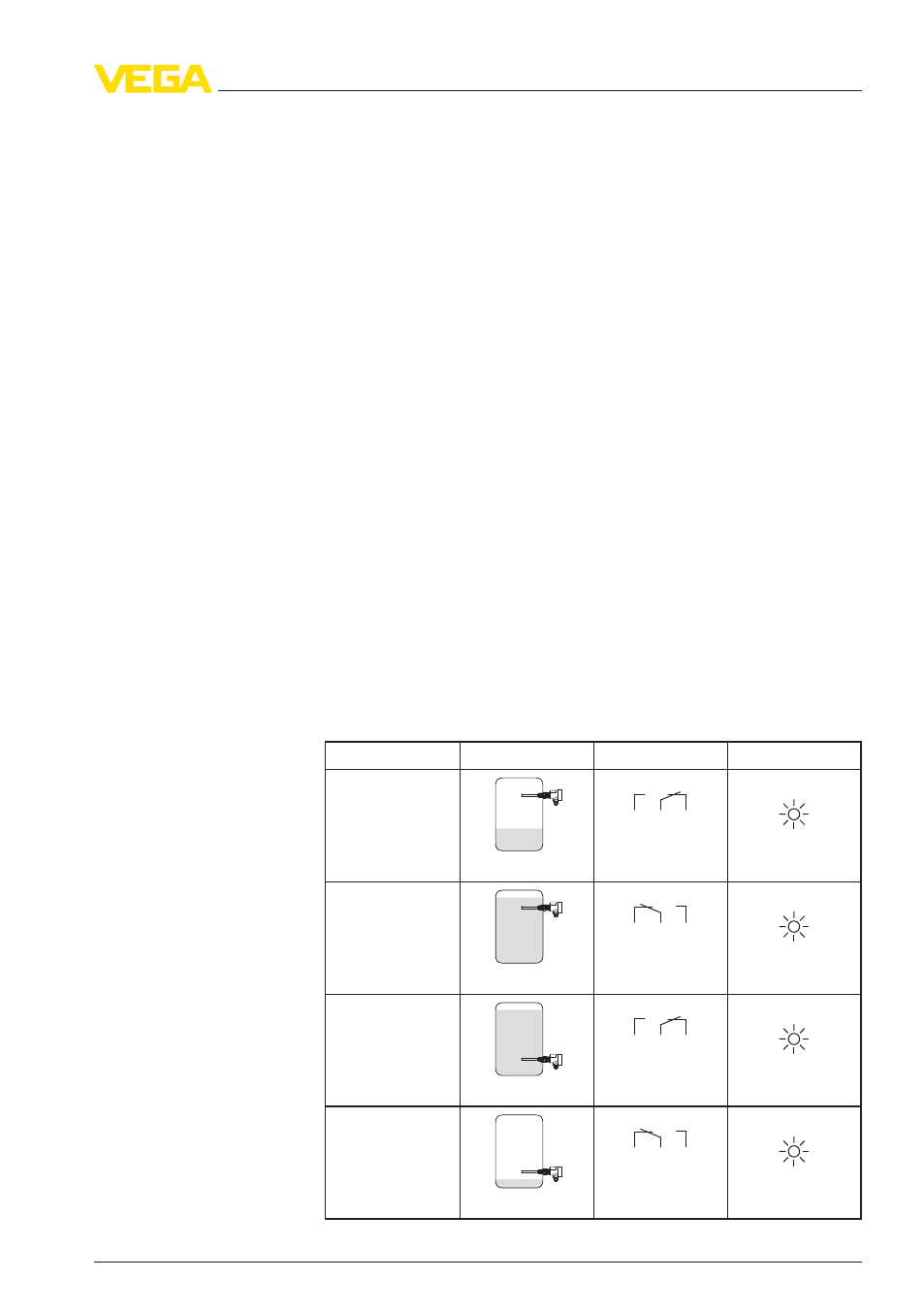
.3 Function chart
The following chart provides an overview of the switching conditions
depending on the adjusted mode and level.
Level
Switching status Control lamp
Mode max.
Overflow protec-
tion
5
3
4
(8)
(6)
(7)
Relay energized
Green
Mode max.
Overflow protec-
tion
5
3
4
(8)
(6)
(7)
Relay deenergized
Red
Mode min.
Dry run protection
5
3
4
(8)
(6)
(7)
Relay energized
Green
Mode min.
Dry run protection
5
3
4
(8)
(6)
(7)
Relay deenergized
Red
Mode adjustment (2)
Signal lamp (5)
VEGAWAVE
61 • - Relay (DPDT)
19
6 Set up
32247
-
EN
-120418