2 connection procedure – VEGA VEGABAR 14 User Manual
Page 12
Warning:
W
ithin galvanic plants as well as vessels with cathodic corrosion
protection there are considerable potential differences. Considerably
equalisation currents can be caused via the cable scrren when the
screen is earthed on both ends. To avoid this, the cable screen must
only connected to ground potential on one side of the switching
cabinet in such applications. The cable screen must not be connected
to the internal ground terminal in the sensor and the outer ground
terminal on the housing not to the potential equalisation!
Information:
T
he metal parts of the instrument (antenna, transmitter, concentric
tube, etc.) are conductive connected with the inner and outer ground
terminal on the housing. This connection exists either directly metallic
or with instruments with external electronics via the screen of the
special connection cable. You can find specifications to the potential
connections within the instrument in chapter "Technical data".
T
ake note of the corresponding installation regulations for Ex
applications.
5
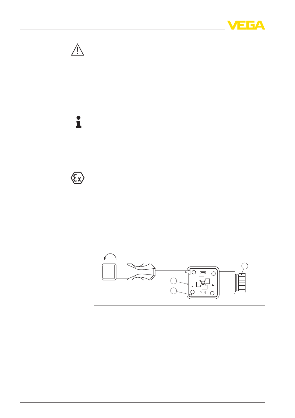
.2 Connection procedure
P
roceed as follows:
1
L
oosen the screw on the rear of the plug connector
2
R
emove the plug connector and seal from VEGABAR 14
3
R
emove the plug insert out of the plug housing
1
2
3
Fig. 3: Loosen the plug insert
1
Cable gland
2
Plug insert
3
Plug housing
4
R
emove approx. 5 cm of the cable mantle, strip approx. 1 cm
insulation from the individual wires
5
L
ead the cable through the cable gland into the plug housing
6
C
onnect the wire ends to the screw terminals according to the
wiring plan
Select connec-
tion cable for Ex
applications
Connection via angle
plug connector
12
VEGABAR
14
5 C
onnecting to power supply
22441
-EN
-111006