5 diagnostics, 1 maintenance, 2 failure rectification – VEGA D96_D97 Profibus PA User Manual
Page 31: Fault signals, Troubleshooting
Pressure transmitter D96/D97 (Profibus PA)
31
Diagnostics
5 Diagnostics
5.1 Maintenance
Pressure transmitter D96 and D97 are main-
tenance-free.
5.2 Failure rectification
Fault signals
The pressure transmitter D96/D97 provides
maximum reliability through its self-test and
continuous self-monitoring. If, however, mal-
functions occur, the pressure transmitter
D96/D97 diagnosis distinguishes between
atypical process conditions and faults in the
pressure transmitter D96/D97.
Atypical process conditions
Exceeding or falling short of measuring
range limits (fault signal extinguishes when
the measured value is again in the measuring
range).
Failure in the D96/D97 pressure transmit-
ter
Failure in the electronics, interference or
damage in the measuring cell.
The following table assists in the analysis of
fault signals.
Cause of
Fault signal via
failure
DOT-matrix
Bar graph
Digital indication
Clearly
"OPERATE
Bar graph 0 %
outside
????
or 100 %
measuring
bar"
digital value
range
flashes
Overload
Bar graph 0 %
range
or 100 %,
of the
digital value
meas. cell
four segments
flash "- - - -"
Failure in
all segments
D96/D97
flash
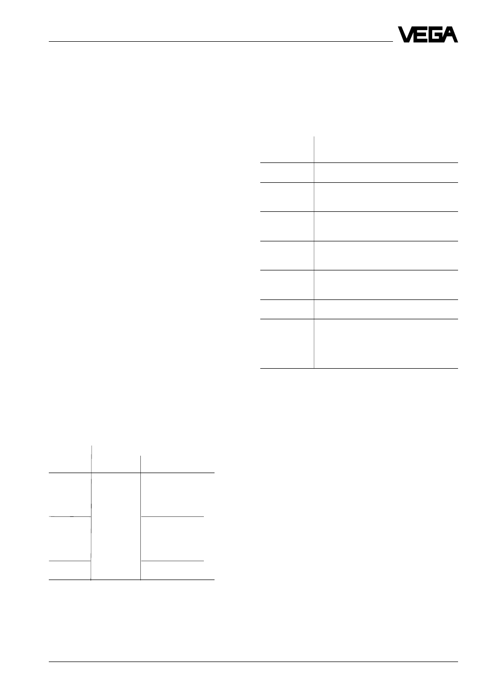
On instruments with menu-driven adjustment
with additional functions, the possible causes
are displayed under the menu item "Diagnos-
tics no." in case of failure.
Diagnostics
Meaning
no.
1
No frequency from C/D-converter
2
Frequency signal of the capacitor not
within the limit values
3
Frequency signal of the reference
capacitor not within the limit values
4
Frequency signal temperature not
within the limit values
7
Communication with EEPROM dis-
rupted
9
Error in EEPROM CRC-checksum
11
Process connection or electronics
module has been exchanged (ap-
pears for approx. 20 s after switching
on for the first time after exchange)
Troubleshooting
If the displayed value does not correspond
to the level in the vessel or to the process
pressure, the following measures must be
taken:
- check the pressure compensation (only
with gauge pressure measuring ranges)
- check the electrical connections.
Checking pressure compensation
Open the processing unit of the pressure
transmitter. The measured value must not
change. However, if the displayed value
changes, compensation of the atmospheric
pressure is not ensured, which can result in
distortion of the measured value. Check the
breather on the processing unit.