6 set up, 1 adjustment system, 2 adjustment elements – VEGA VEGATOR 256C User Manual
Page 13: 3 switching point adjustment, Turn potentiometer (2) to position 0
6 Set up
6.1 Adjustment system
0
10
8
7
6
5
4
N
L1
3
2
1
max.
min.
R
200...250VAC 3VA
power supply Relais: max 250V, 5A, 750VA
1
2
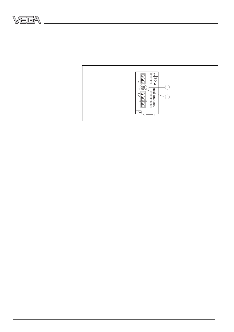
Fig. 5: Indicating and adjustment elements
1
Signal lamp - Relay output
2
Potentiometer for switching point adjustment
6.2 Adjustment elements
The yellow relay control lamp (LED) shows the switching
condition of the relay.
In general, the relay control lamp indicates the activated
(energised) condition of the relay.
A dark relay control lamp means that the relay is deenergised.
A potentiometer for switching point adaptation is located on the
front plate of the signal conditioning instrument. With this
potentiometer you can adapt the measuring system to the
conductivity of the product.
6.3 Switching point adjustment
l
Connecting the signal conditioning instrument to voltage
supply
l
Turn potentiometer (2) to position 0
l
Fill the vessel until the max. probe is covered approx. 1 cm
by the product
l
Turn the potentiometer (2) slowly clockwise until the yellow
LED extinguishes
The switching sensitivity of the signal conditioning instrument
is now adapted to the conductivity of the product.
Control lamp
Potentiometer for switching
point adjustment
Level detection
VEGATOR 256C - Signal conditioning instrument
13
Set up
23409
-EN
-070316