2 mounting, 1 mounting instructions, Mounting carrier – VEGA VEGATOR 521, 522, 523, 527 User Manual
Page 7: Mounting single housing, Coding
VEGATOR
7
Mounting
2 Mounting
2.1 Mounting instructions
VEGATOR can be mounted either in a card
slot in a carrier BGT 596 or in a single
housing type 505.
Card slot
Multipoint connector DIN 41 612, series F, 33-
pole (d, b, z) with coded pin and mounting
material for mounting in carrier BGT 596.
Card slot Ex
Multipoint connector DIN 41 612, series F, 33-
pole (d, b, z) with coded pins, Ex separating
chamber and mounting material for mounting
in carrier BGT 596 Ex.M.
Single housing
Plastic housing type 505 for individual
mounting of signal conditioning instruments
with instrument width 5 TE (25.4 mm).
Mounting carrier
Mount the respective module (standard or Ex
version) on your carrier BGT 596. Wire the
connections of the multipoint connector
according to the connection schematic on the
following page.
The multipoint connector is available as
follows:
- Wire-Wrap standard connection
1.0 x 1.0 mm
- Plug connection 2.8 x 0.8 mm
- Termi-Point standard connection
1.6 x 0.8 mm
- Soldering connection
- Screw terminals 2 x 0.5 mm
2
For further information on mounting, use the
operating instructions of the carrier.
Mounting single housing
The socket can be either screwed directly to
the mounting plate or plugged to a carrier rail
(TS 35 x 7.5 acc. to EN 50 022 or TS 32 acc.
to EN 50 035). Connect the terminals of the
basic plate according to the connection
schematic on the following page. For further
information on mounting, use the operating
instructions of the housing.
Coding
To prevent inadvertent swapping of the
various instruments, the multiple plug of the
instrument is provided with one or several
coding holes.
By means of a fixed coded pin on the Ex
module, it is ensured that only Ex instruments
can be inserted.
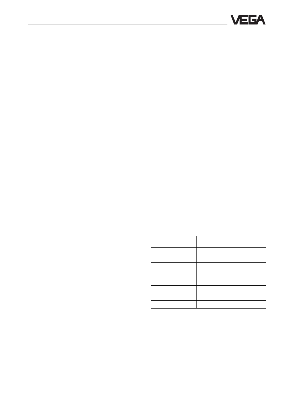
To prevent inadvertent swapping of the
various instruments, two additional coded
pins are included with the instrument. Insert
these coded pins into the predetermined
holes on the multipoint connector. The coded
pins must be inserted into the following
positions:
Instrument
Ex coding
coding
VEGATOR 521
a9 / c7
––
VEGATOR 521 Ex
a9 / c7
c23
VEGATOR 522
a11 / c7
––
VEGATOR 522 Ex
a11 / c7
c23
VEGATOR 523
a13 / c7
––
VEGATOR 523 Ex
a13 / c7
c23
VEGATOR 527
a15 / c7
––
VEGATOR 527 Ex
a15 / c7
c23