Ex version, Wiring of the transistor outputs, Vegator 523 (ex) – VEGA VEGATOR 521, 522, 523, 527 User Manual
Page 10: Vegator 527 (ex), Electrical connection, Example vegator 527 ex), The resistor r, Is used as short-circuit protection example: u, 24 v, u, 5 v, i
10
VEGATOR
2
6
20
28
24
22
10
16
18
30
32
d b z
+
-
+
-
+
-
+
-
12
+
-
+
-
+
-
+
-
L1 (+)
N (-)
Electrical connection
Power
supply
Level transistor 1
Fail safe transistor
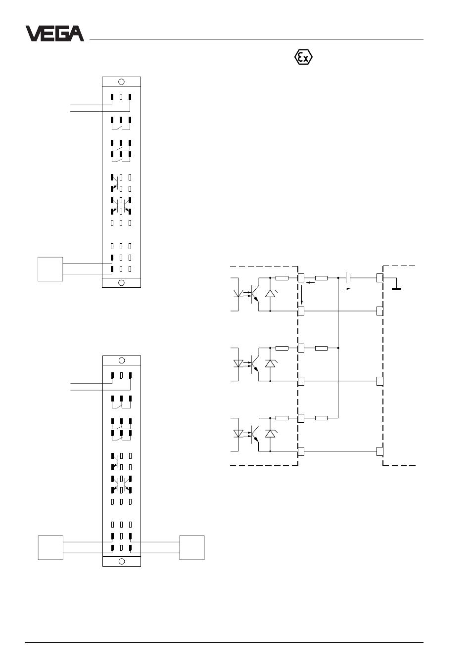
Ex version
Please note the instructions in the attached
approval documents as well as the valid
installation regulations for connection of Ex
certified instruments.
Keep in mind that the Ex separating chamber
must be mounted on the multipoint connector.
Always lead the cables through the Ex
separating chamber. Check also the
operating instructions of the carrier BGT 596
Ex.M and the Ex instructions on page 8.
Sensor 1
Sensor 2
Fail safe relay
Level relay 1
Level relay 2
Level transistor 2
Wiring of the transistor outputs
(example VEGATOR 527 Ex)
+
±
±
+
+
±
+
+
±
+
The resistor R
S
is used as short-circuit
protection
Example:
U
B
= 24 V, U
CE
- 1.5 V, I
B
= max. 60 mA
U
B
– U
CE
24 V – 1.5 V
R
S
= ––––––––– = ––––––––––––– = 375
Ω
I
B
60 mA
VEGATOR 527 Ex
PLC
0.1
0.2
0.3
I
B
U
C E
R
S
R
S
VEGATOR 523 (Ex)
Power supply
Sensor 1
Fail safe relay
2
6
20
28
24
22
10
16
18
30
32
d b z
+
-
+
-
+
-
+
-
12
+
-
+
-
L1 (+)
N (-)
Level relay 1
Level relay 2
Level transistor 2
Level transistor 1
Fail safe transistor
VEGATOR 527 (Ex)