3 communication structure, 3communication structure, Addressing of the measured value – VEGA VEGASCAN 850 Modbus signal output User Manual
Page 5
Modbus signal output VEGASCAN 850
5
0
30001
2
30003
4
30005
6
30007
8
30009
10
30011
12
30013
14
30015
504
30505
506
30507
508
30509
16
30017
4 Byte
Register
address
in
Modicon
DCS output 2
DCS output 1
DCS output 3
DCS output 4
DCS output 5
DCS output 6
DCS output 7
DCS output 8
DCS output 9
DCS output 58
DCS output 59
DCS output 60
High-
Byte
Low-
Byte
Unit
Sta-
tus
Meas. value
Add. info
Register
address in
VEGASCAN
850
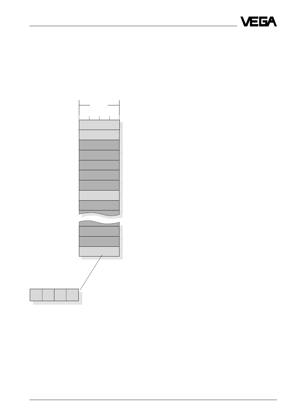
Addressing of measured values
Addressing of the measured value
The measured value image is always sorted
according to DCS outputs. The following
illustration shows the addressing of the inter-
mediate storage via Modbus.
Note:
A complete overview on the process image
of the measured values of VEGASCAN 850 is
given in chapter "1.7 Measured value image“.
3
Communication structure
Within the data communication between
VEGASCAN 850 and the connected process
data processing, the following functions are
supported:
- Mode (VEGASCAN 850 is Slave)
- Instrument address (default value # 1)
- Enquiries:
Function 01, Read Coil Status
Function 02, Read Input Status
Function 04, Read Input Register(s)
- Diagnostic
Function 08, Loop back Diagnostic
The RTU mode or the ASCII mode are used
as transmission mode.
Here, each DCS value transmitted by
VEGASCAN is represented by one register
address (= 2 register words = 4 Byte):
- 2 Byte indication value
- 1 Byte unit of measurement (is filled with 0)
- 1 Byte status information
The decimal point as well as the measure-
ment unit of the DCS value are transferred by
VEGASCAN to the Modbus.
This information must be completed by the
user with the software of the process data
processing.
Contents enquiry telegram
(Modbus master –> VEGASCAN 850):
• Instrument address VEGASCAN on Mod-
bus
• Function code
• Address of the 1. register (Modicon regis-
ter memory)
• Number of registers
• Check sum (error control)
Contents answer telegram
(VEGACOM 557 –> Modbus master):
• Instrument address VEGASCAN on Mod-
bus
• Function code
• Number of register data bytes
• Register data
• Check sum (error control)
Communication structure