2 data image in vegascan 850, 2data image in vegascan 850 – VEGA VEGASCAN 850 Modbus signal output User Manual
Page 4
4
Modbus signal output VEGASCAN 850
on
PC
VEGALOG
571
!
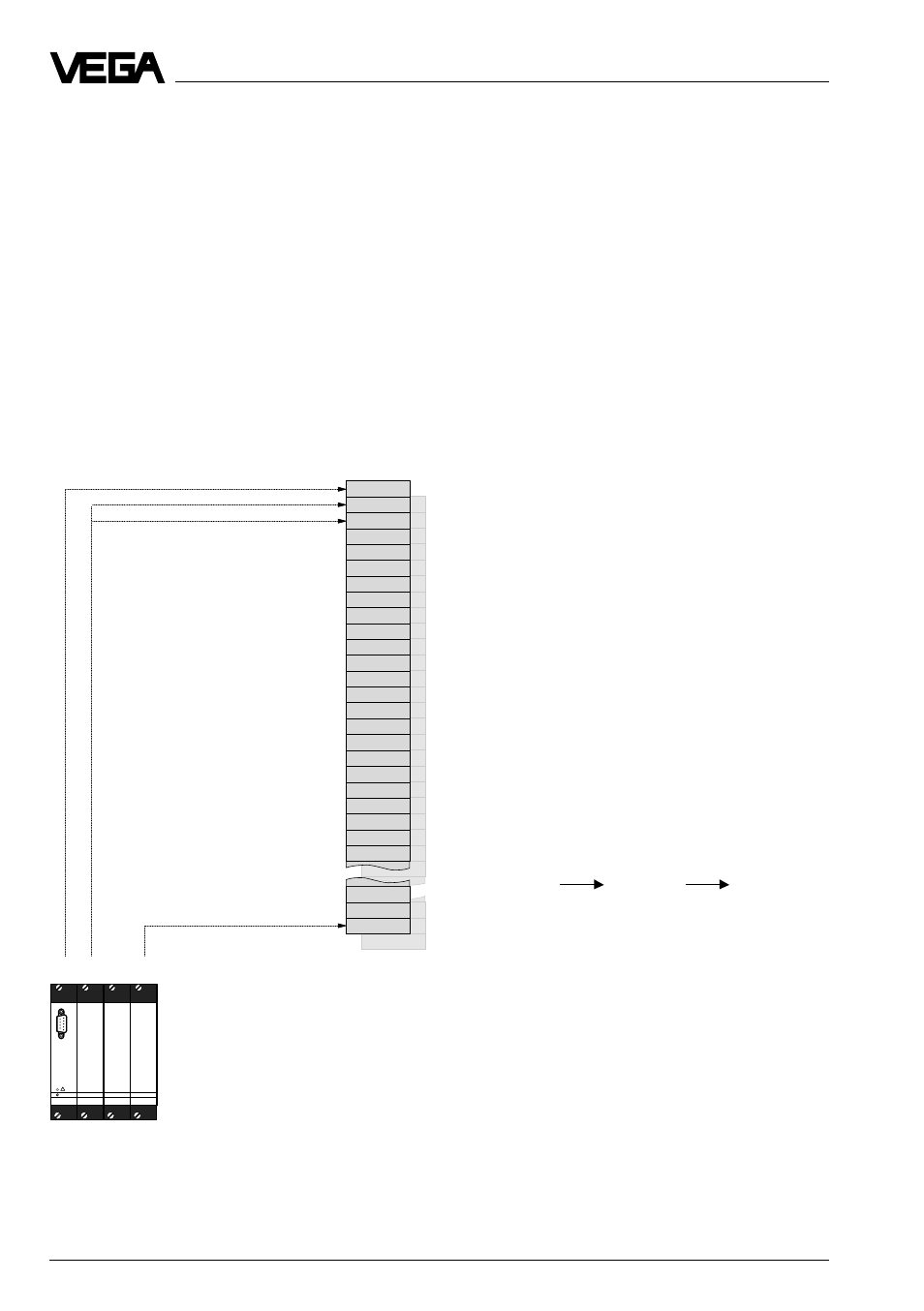
Measured value image
DCS output 1
DCS output 2
DCS output 3
DCS output 260
Meas.
value
z
Meas.
value
x
Meas.
value
y
2
Data image in VEGASCAN 850
Addressing of measured values in Modbus
systems is "word-orientated“. In VEGASCAN
850, one measured value is represented by
two words, the first word includes the real
measured value, the next higher word, the
respective status information. In the stand-
ard, the term register word is used instead of
the term word. The addressing is made ei-
ther via existing library enquiries of a PLC
(e.g. Modicon) or by direct generation of the
Modbus telegrams.
Examples of valid register word addresses
are shown in the next illustration. Especially
when using Modicon, make sure that the
register address for the library enquiry is by
1 higher than the transmitted address on the
Modbus.
VEGASCAN 850 can administrate up to 60
measurement loops. For transfer of meas-
ured values of a measurement loop,
VEGASCAN provides up to 60 DCS outputs.
One or several DCS outputs with individual
index can be assigned to each of these
measurement loops. The configuration of
VEGASCAN 850 is made with the VEGA
adjustment software VVO. You define via the
chosen PC/DCS output, where the respective
measured values can be collected within the
intermediate storage in VEGASCAN 850.
Note:
When addressing register words, all ad-
dresses between 0 and 65535 can be used
with VEGASCAN 850. VEGASCAN 850 uses
for access to the intermediate storage gener-
ally the last 3 digits of the address.
This results in the following conversion table:
Register
Register
Register
address in
address on
address in
Modicon
Modbus
VEGASCAN
850
30 001
30 000
000
30 017
30 016
016
34 001
34 000
000
34 017
34 016
016
Data image in VEGASCAN 850