Soft dB SPM PLL User Guide User Manual
Page 7
SPM - PLL User’s Manual
7
2
Theory of Operation
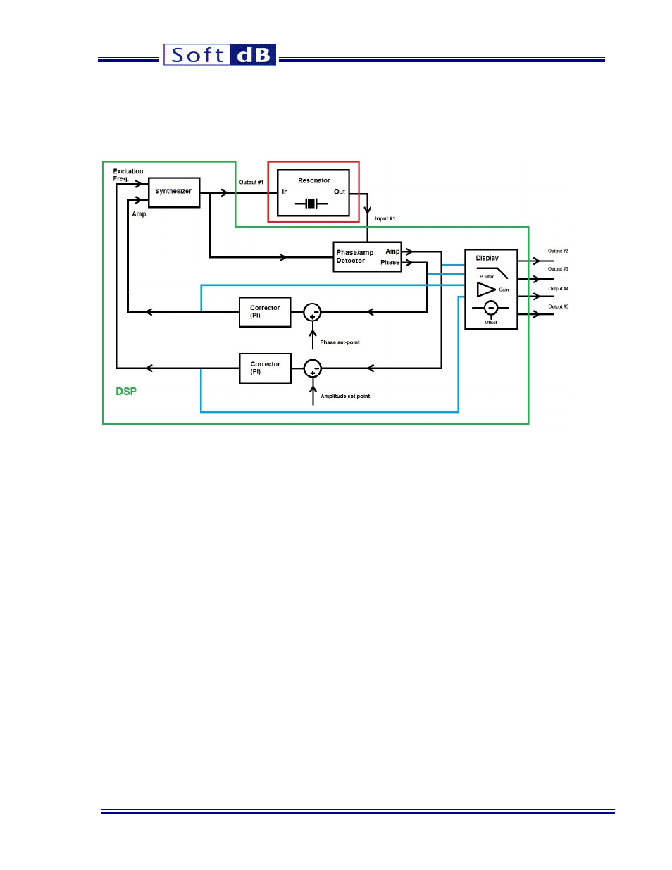
The diagram of PLL running on the Signal Ranger Mk3 DSP board is illustrated in the following figure:
PLL schematic
The synthesizer sends a sine wave on output #1. Input #1 measures the output of the resonator. The
phase detector measures the amplitude and the phase of the resonator output signal, with respect to its
excitation. The phase detector algorithm measures the phase of the resonator alone, automatically
correcting for the phase of board’s digital and analog chains. So, no special calibration is necessary
before using the PLL. When working with a second-order resonator, specifying a phase of -90 degrees
will lock the PLL at precisely the resonance frequency.
The amplitude and phase control loops keep the resonator phase and output amplitude at specific set-
points.
The PLL can generate up to four analog signals on outputs #2, #3, #4 and #5. The possible selections
for these signals are:
The resonator phase
The resonator amplitude
The excitation amplitude
The excitation frequency
For each signal, the gain (or the range) can be specified to obtain the desired output sensitivity. Also,
an adjustable low pass filter is added to increase the resolution of the output signals if necessary. An
offset (reference) can be added so the analog output signal is centered on a user-selectable value.
The PLL is controlled and adjusted using a graphical user-interface running on a Windows PC.