Ohaus VX SERIES FLOOR SCALES Manual User Manual
Page 7
VX Series Floor Scale EN-3
Connecting the Platform Cable
1. Remove the two fasteners on the junction box access cover located on the side panel of the platform.
2. Slide the junction box forward and out of the compartment. Remove the plastic top cover from the junction box.
3. Loosen the water-tight gland that does not have a cable inserted. Insert about 6”
(150mm)
of the cable through the gland
and into the junction box.
4. At the junction box end strip the outer jacket of the cable 1.5”
(40mm) then
strip 0.25”
(6mm)
from each single wire end.
5. On the cable determine which wire connects to the cable’s shielding. This is normally a Bare wire. Optionally the shield
may be twisted into a pig-tail. This shield connection must always be connected to the point marked “SHIELD” or “GND”.*
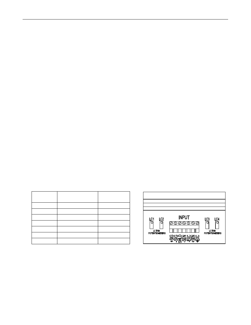
6. Connect the wire ends to the “INPUT” terminal block inside the junction box, see Figure 2. The Shield wire must be
connected to the connection marked “SHIELD”. The remaining wire colors may be connected to the terminal block in any
arrangement though a recommended color chart is shown below in Table 1. If a label is attached to the cable follow the
color code listed on the label instead.
7. After making all connections make a record of the wire color to signal names. This information will be needed when
connecting the Indicator to the other end of the cable.
8. Route the other end of the cable into the platform’s junction box compartment and pass it out through the rear opening.
9. Reinstall the plastic top to the junction box, tighten the water-tight gland around the cable, return the junction box to the
internal compartment, reinstall the external cover and fasteners.
10. Route the cable out from under the platform to the location where the Indicator will be mounted. Ensure that the cable will
be protected against possible damage when routed to the Indicator.
11. The cable near the platform must lie free without tension. Excessive tension may result in weighing errors.
Figure 2. Junction Box Terminal Block.
*Note: The standard cable included with the VX Floor Scale will have either a Bare wire or a Yellow wire connected to the Shield. On
some cable assemblies a label may be attached listing the Shield wire and the recommended wire color connections.
TABLE 1. RECOMMENDED WIRE COLOR
TO SIGNAL NAME CONNECTIONS
Function
Indicator Cable Wire
Colors
Load Cell Wire
Color
- Signal
Black
White
+ Signal
Green
Green
- Sense
Red
Not used
- Excitation
Blue
Black
+ Sense
Yellow
Not used
+ Excitation White
Red
Shield
Orange
Braided