Block diagram of transceiver – Lynn Electronics MC-SFP-10km User Manual
Page 4
www.lynnelec.com
MC-SFP-10km
1310 nm Single-mode Transceiver, 10.5dB margin
Small Form Pluggable (SFP), 3.3 V
1.0625Gbd Fiber Channel/1.25 Gigabit Ethernet
TEC Opitx Solutions
Division of Lynn Electronics Corp.
154 Railroad Drive • Ivyland, PA. 18974
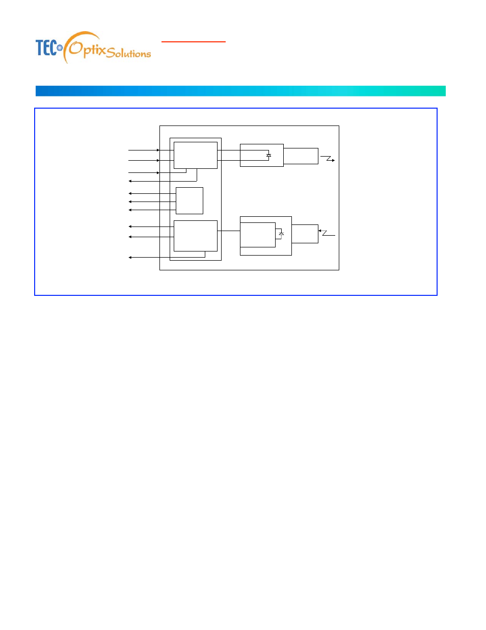
Block Diagram of Transceiver
POST-Amp
&
LOS Detect
LD Driver
&
Fault Sense
RRE-
AMPLIFIER
IC
LASER
DATA
DATA/
DATA
DATA/
ELECTRICAL SUBASSEMBLY
OPTICAL
SUB-
ASSEMBLIES
Photo
Diode
DUPLEX SC
RECEPTACLE
RX_LOS
TOP VIEW (Label side)
MOD_DEF
(0)
(1)
(2)
TX_DISABLE
TX_FAULT
Transmitter Section
The transmitter section consists of a 1310 nm InGaAsP laser in an eye safe optical subassembly (OSA) which mates to the fiber
cable. The laser OSA is driven by a LD driver IC which converts differential input LVPECL logic signals into an analog laser
driving current.
TX_FAULT
When sensing an improper power level in the laser driver, the SFP set this signal high and turns off the Laser. TX_FAULT can be
reset with the TX_DISABLE line. The signal is in TTL level.
TX_DISABLE
The TX_DISABLE signal is high (TTL logic “1”) to turn off the laser output. The laser will turn on within 1ms when
TX_DISABLE is low (TTL logic “0”).
Receiver Section
The receiver utilizes an InGaAs PIN photodiode mounted together with a trans-impedance preamplifier IC in an OSA. This OSA
is connected to a circuit providing post-amplification quantization, and optical signal detection.
Receive Loss (RX_LOS)
The RX_LOS is high (logic “1”) when there is no incoming light from the companion transceiver. This signal is normally used by
the system for the diagnostic purpose. The signal is operated in TTL level.