Front panel & pedal board bracket assembly, Dunlop manual - mc403 power system, Hardware checklist – Dunlop Manufacturing MC403 User Manual
Page 2: 4/4 color print onto cover stock
USA/ Canada
NEMA 5-15P AC male plug
IEC 60320 C13 AC female connector
SJT 18AWG*3C, 2m/78.7in (L)
Europe
CEE 7/7 AC male plug
IEC 60320 C13 AC female connector
H05VV-F 0.75*3C, 2m/78.7in (L)
Japan
JIS C 8303 AC male plug
IEC 60320 C13 AC female connector
VCTF 0.75*3C, 2m/78.7in (L)
Australia
SAA power cord, AS3112 AC male plug, 10A
IEC 60320 C13 AC female connector
2m/78.7in (L)
UK
NEMA 5-15P AC male plug
IEC 60320 C13 AC female connector
H05VV-F 0.75*3C, 2m/78.7in (L)
HARDWARE CHECKLIST
Unpack the contents of the box and check that the following was included:
One (1) MC403 Power System
One (1) MC403 instruction manual
One (1) 19” rack front panel
Two (2) pedalboard mounting brackets
Twenty (20) cables:
Four (4) 2.1 x 5.5mm black right angle to straight, 1’ long
Eight (8) 2.1 x 5.5mm black right angle to straight, 2’ long
Four (4) 2.1 x 5.5mm black right angle to straight 3’ long
Two (2) 2.5 x 5.5mm red right angle to straight 4’ long
One (1) 2.1 x 5.5mm to 3.5mm black straight 2’ long
One (1) 2.1 x 5.5mm to 3.5mm black straight 3’ long
One (1) AC cord with appropriate connector for region of operation:
DIRECTIONS
(1) Set the red AC 115/230 input selector to your local AC voltage.
(2) Plug the included AC power cord into the AC IN jack.
(3) Connect the AC cord into a wall outlet.
(4) Flip the ON/OFF switch to the ON position. A red LED on the rear panel will light
up to indicate the unit is active.
(5) Read the OUTPUT GUIDE on the following pages to make sure you are using the
correct output jacks and cables.
(6) Connect pedals to the MC403 using supplied cables. The red LED above
each output jack will light to indicate that power is being supplied to the
connected
pedal.
(7) An AC THRU jack is located next to the AC IN jack to provide auxiliary power
to another device.
DO NOT EXCEED 200 WATTS on AC THRU device!
OUTPUT GUIDE
Before plugging anything into the MC403 Power System, check that the power
requirements of the device match the output capabilities of the MC403.
Specifically, you should check:
(1) The device’s voltage requirement to match the MC403 output voltage.
(2) Whether the device uses AC or DC.
(3) The current requirement to not exceed the MC403’s MAX CURRENT spec.
(4) The polarity when using DC power.
The cables provided with the MC403
support the industry standard positive (+)
barrel and negative (-) center polarity.
If you are unsure about what power your device requires,
DO NOT PLUG THE DEVICE INTO THE MC403!
The following list provides usage
examples for each of the output types available on the MC403.
ADJUSTABLE DC OUTPUTS – Use 2.1 x 5.5mm black cables.
Push the red button IN for the high voltage (10.5-15V) setting.
Push the red button OUT for the low voltage (6.5-10.5V) setting.
Rotate the black adjustment knob to fine tune the value.
To simulate a dying battery tone on a transistor based distortion/fuzz/overdrive,
set the red button OUT and rotate the adj. knob until desired tone is achieved.
Radial
™
Tonebone
™
pedals requiring 15VDC, 400mA can be used with the red
button IN and the adjustment knob rotated fully clockwise.
9VAC OUTPUTS
– Use 2.5 x 5.5mm red cables.
Line 6
®
Stomp Modeler and POD
®
units (excluding Pocket POD
®
)
9VDC OUTPUTS – Use 2.1 x 5.5mm black cables.
MXR
®
, Crybaby
®
, Way Huge
®
Electronics pedals requiring Dunlop ECB-003
Dunlop
®
UV1SC Stereo Chorus, JD4S Rotovibe
Boss
®
pedals requiring PSA-series adapters
Electro-Harmonix
®
pedals requiring 9DC-100 adapter
Maxon
®
pedals requiring AC210N adapter
Ibanez
®
pedals requiring AC109 adapter
Radial
™
pedals requiring 9VDC, 40mA negative center adapters
Line6
®
ToneCore
®
series pedals
DigiTech
®
pedals requiring PSR200R
18VDC OUTPUTS – Use 2.1 x 5.5mm black cables.
MXR
®
, Crybaby
®
pedals requiring Dunlop ECB-004
Dunlop
®
UV1 Univibe
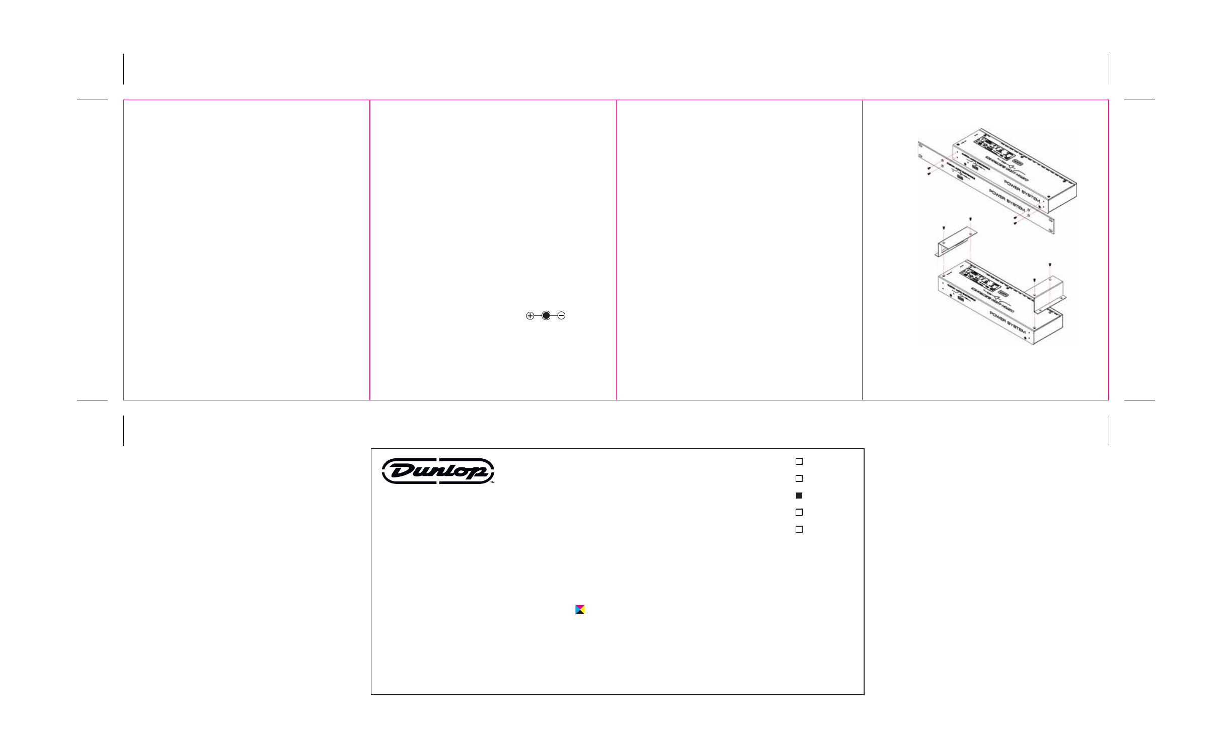
FRONT PANEL & PEDAL BOARD BRACKET ASSEMBLY
Remove the four screws on front of unit as indicated in Figure A for rack mounting
or as in Figure B for pedalboard mounting. Place the brackets on the unit, line up
the holes, and replace screws to secure brackets. Use M3.0x0.5, L=8mm (max)
screws if factory screws are lost.
Figure B – Pedalboard Mount
Figure A – Rack Mount
Dunlop Manual - MC403 Power system
4/4 color Print onto Cover Stock
DUNLOP PART #:
92503008461
UPC #:
N/A
FILE NAME:
92503008461-MC403_MANUAL.EPS
FILE LOCATION:
CREATIVE ARCHIVE
PROJECT DIRECTOR:
JIM SILVA
DESIGNER:
HANK ALVA
CONTACT:
DIMENSIONS:
4” W X 4.875” H FOLDED, 16” W X 4.875” H OPEN
PRINT MATERIAL:
100# DULL COVER
PRINTING SIDE 1:
1/C
PRINTING SIDE 2:
4/C
PROCESS COLORS:
4 COLOR PROCESS
LINE COLORS:
N/A
FONTS:
N/A (ALL FONTS HAVE BEEN MADE ART)
LINKED IMAGES:
N/A
NOTES:
SCORE AND FOLD AT CENTER AS INDICATED
APPROVED BY:
JIM SILVA
DATE: 03/11/09
DUNLOP MANUFACTURING, INC.
150 INDUSTRIAL WAY
P.O. BOX 846
BENICIA, CA 94510
PHONE: 707.745.2722
FAX: 707.745.2658
WARNING: The information contained in this
document is the intellectual property of
Dunlop. Any use and/or reproduction, in
whole or in part, must have the written
permission of Jim Dunlop Manufacturing, Inc.
CONCEPT
REVISED
PROOF
QUOTE
FINAL ART