Enc 250 – ACU-RITE ENC 250MS User Manual
Page 5
Acu-Rite Companies Inc.
ENC 250
™
MULTI-SECTION
4
Machine
casting
A variety of mounting conditions can be accommodated.
• The machine configuration determines the brackets
required to install the encoder.
• Two typical mounting conditions are shown; reading head
mounting plate, and a three piece combination assembly for
mounting the reading head to the machine.
• The [8-32] 4mm SHCS for mounting the reading head is a
standard low head style fastener, supplied with the
mounting hardware.
• Tool requirements are listed on page 2.
• Due to the long length of the encoder sections, the
installation illustrations have been modified.
In most cases, the sections have been shorten to
accommodate the information that they are presenting.
Please keep this in mind as the encoder is being installed.
• This combination typically applies to a lathe where the
cross feed over hangs the bed mounting surface.
• A wide range of combination lengths are available.
Three piece combination bracket ...
• The mounting plate typically applies to surfaces that are
flush, or slightly offset.
Reading head mounting plate ...
Machine
axis
Machine
casting
Mounting plate
ENC 250 encoder
Encoder reading
head
Machine
axis
Combination
bracket
assembly
ENC 250 encoder
Encoder reading
head
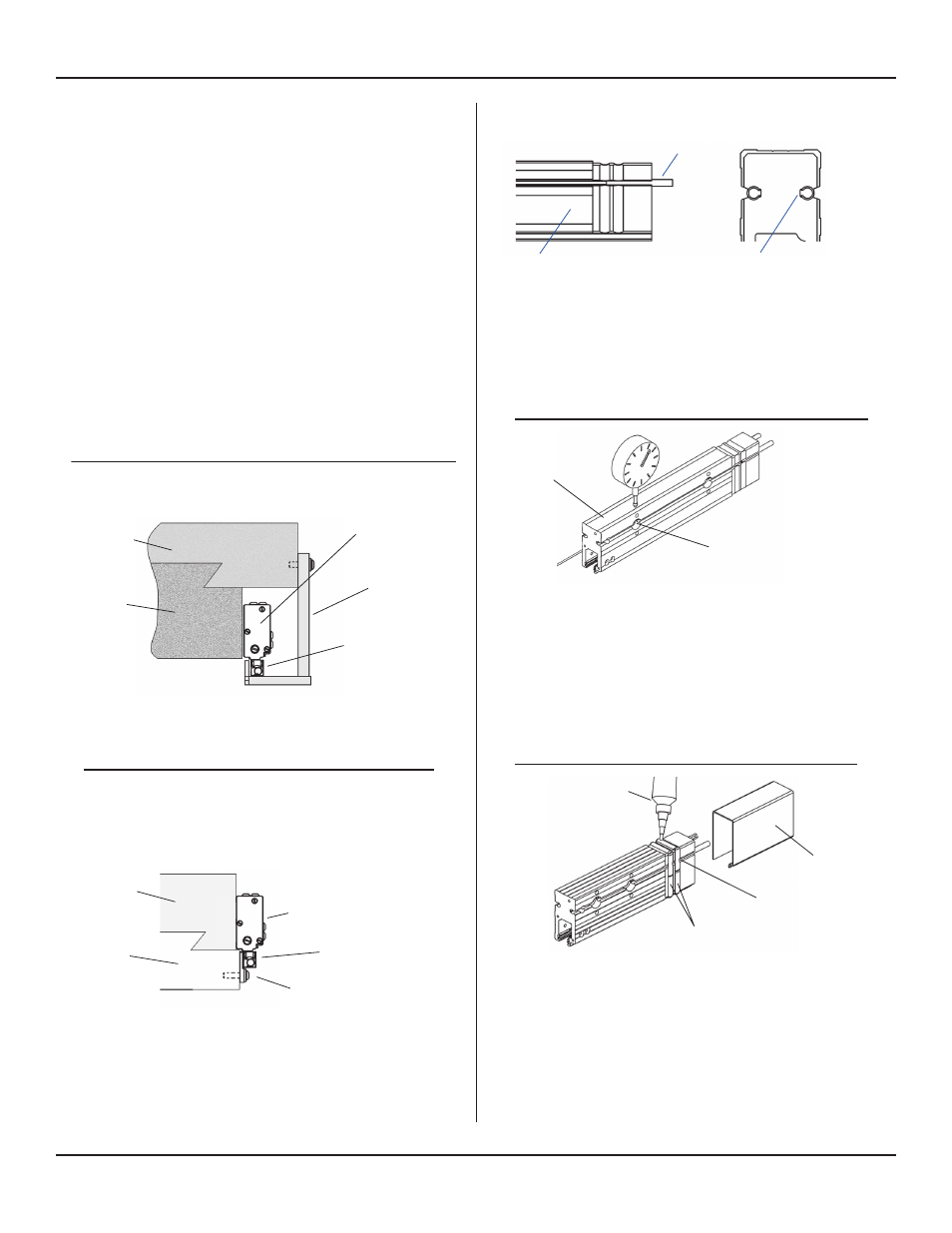
• Tap two roll pins into the extruded slots in the “left end
section” as shown. Pins should protrude approximately [5/8”]
15.87mm.
• The seams on the roll pins face towards the inside of the
scale case.
• Repeat this step for all middle scale sections, inserting the
roll pins into the right end of each.
Insert roll pin with open slot
facing in as shown
Roll Pin
Enlarged end
view
Left end section
• Apply RTV Silicone Rubber to the two sealant grooves in
the left end section. The sealant must be applied on all
three sides of the case. Seal the seated ends of the spring
pins. Keep the end and inside of the section free of
sealant.
• Slide the scale clip over the end of the scale section to the
stop machined in the scale case. There is sufficient spring
in the clip to clamp it securely around the case.
• Clean off any excess RTV on the outside of the case.
Seated end of pin
Scale clip
• Hold the left end section against the selected mounting
surface and transfer punch one mounting hole.
• Remove section, drill and tap the location for a
[1/4-20 x 1/2”] M6 x12mm deep minimum.
• Attach the section to the machine, and align the top
surface to within [.012”] .3mm of the axis travel.
Measuring directly over each mounting hole location.
• Transfer punch the second mounting hole. Remove the
section; drill and tap second hole location for a
[1/4-20 x 1/2”] M6 x12mm deep.
Transfer punch (1)
mounting hole location to
the machine surface
Left end
section
Mounting Requirements
Scale Case Installation Procedure
Sealant groves (2)
Left end section installation
RTV