No transmission error with extended response, Acr30 – ACS ACK30 Smart Keyboard User Manual
Page 15
ACR30 Reference Manual
Version 3.3 January 2009
Page 15 of 44
ACR30
Data Length
Number of subsequent data bytes (0 < N < 255)
Data
Data contents of the command.
For
a READ_DATA command, for example, the data bytes would contain the contents
of the memory addresses read from the card. The data bytes can represent values
read from the card and/or status information.
Checksum
The checksum is computed by XORing all response bytes including header, status
bytes, data length and all data bytes.
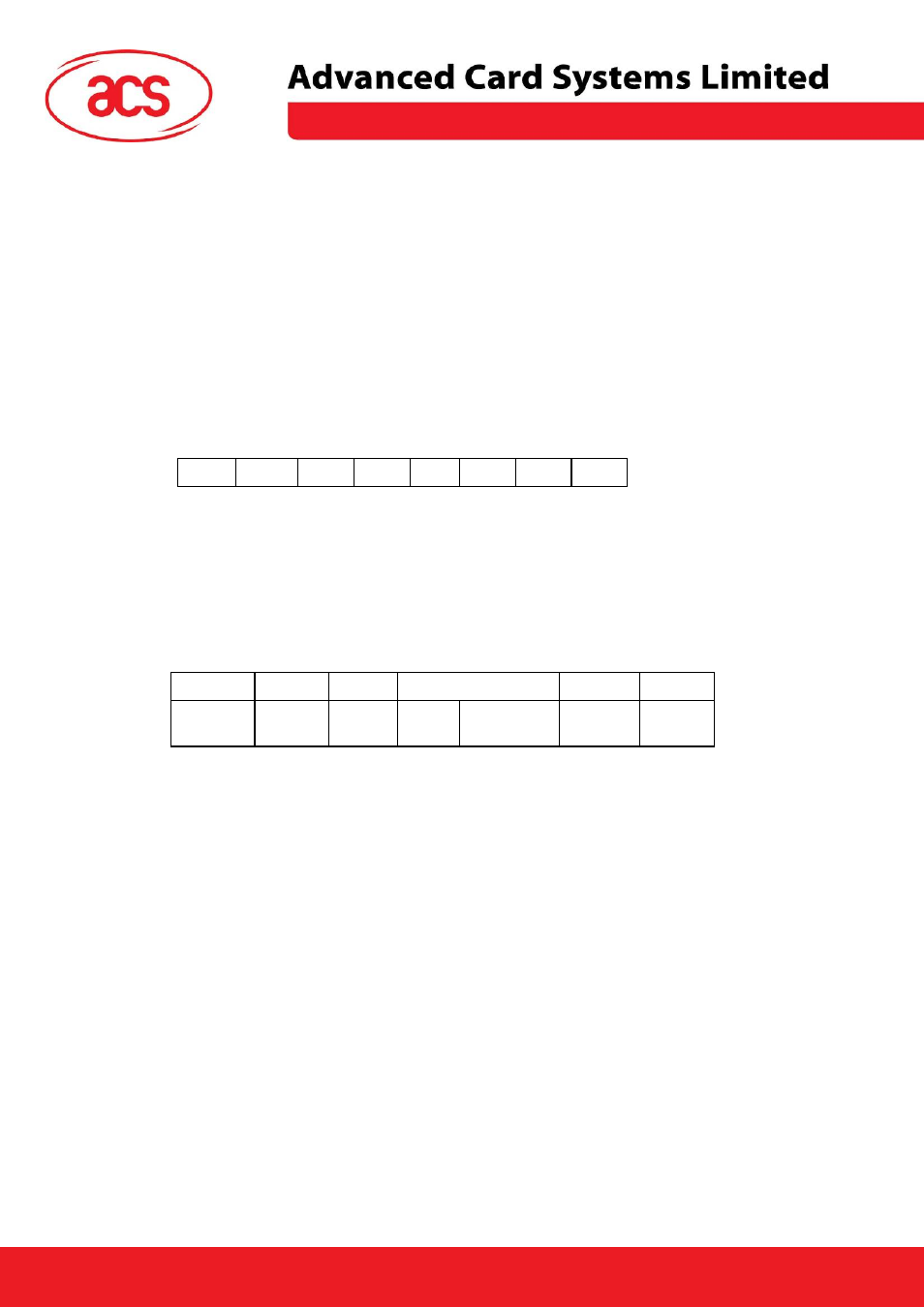
The following example shows the structure of the response to a command which has successfully
been executed and which returns three data bytes with the values 11
H
, 22
H
and 33
H
, respectively:
byte
1 2 3 4 5
6 7 8
01
H
90
H
00
H
03
H
11
H
22
H
33
H
92
H
8.2.2.
No transmission error with extended response
The response by the ACR30 to a correctly received command consists of three protocol bytes, two
status bytes and a variable number of data bytes and has the following structure:
byte
1
2
3
4
5
6
7 ... N+6
(N>0)
N+7
Header
SW1
SW2
Data length = N
Data
Checksum
FF
H
Data
Length
N
Header
Always
01
H
to indicate the start of the response.
SW1
Indicates the command execution status:
90
H
= command
successfully
executed
60
H
= error in command data; command cannot be executed
67
H
= error detected in command execution
FF
H
= status message initiated by the reader
SW2
Further qualification of the command execution status.
A table listing the possible values of the status bytes SW1 and SW2 and the
corresponding meaning is given in Appendix B.
Data Length
Number of subsequent data bytes, and is encoded in 3 bytes. The first byte is FF
H
.
The second byte and the third byte represent data length N.
Data
Data contents of the command.
For
a READ_DATA command, for example, the data bytes would contain the contents
of the memory addresses read from the card. The data bytes can represent values
read from the card and/or status information.