ACR&Artex DGL-1 User Manual
Page 34
ARTEX PRODUCTS / ACR ELECTRONICS, INC
DESCRIPTION, OPERATION, INSTALLATION AND MAINTENANCE MANUAL
DGL-1, DONGLE (453-4010)
25-69-01
Page 34 of 44
JUN 27/12
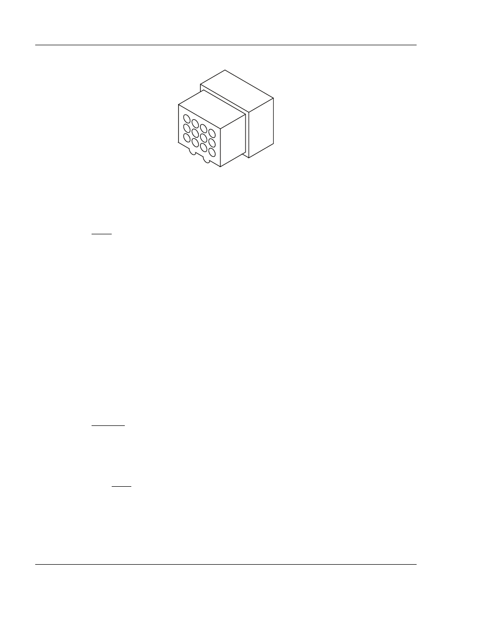
Figure 6. Molex 12-Pin Connector Harness Arrangement
(4)
Assemble the wire harness with the Dongle wire harness (P/N 611-4010). See "Figure 8.
Dongle Wiring Diagram", on page 36.
NOTE: Remote switch pin numbers are for an ARTEX standard remote switch (P/N 345-
6196-04).
(5)
Terminate wires from the horn and remote switch with the male terminal pins provided (P/N
151-6627).
(a)
Strip approximately 0.15 in. (3 mm) of insulation from ELT receptacle end of the wires
from the horn and remote switch.
(b)
Dress and tin the bare wire ends to prevent the strands from fraying during terminal
crimping operations.
(c)
Install the terminal pins with a Molex crimp tool (Molex Tool P/N 63811-330), or
equivalent.
(6)
Insert the terminated wires into the applicable locations in the rectangular 12 position
connector.
(7)
Fabricate a power wire of sufficient length to reach from the red, un-terminated wire on the
preassembled wire harness to a suitable aircraft +28VDC, switchable power source. See
"Figure 7. Molex Power and Ground Wires", on page 35.
CAUTION:
DO NOT WIRE DONGLE DIRECTLY TO THE AIRCRAFT BATTERY. THE 28 VOLT
DC POWER SOURCE SHOULD BE PROTECTED WITH A .5A FUSE, OR CIRCUIT
BREAKER, AND ON A SWITCH BUS.
(a)
A Raychem solder sleeve splice (Raychem P/N D-1744-01) is provided for this
connection.
NOTE: Refer to Raychem for specific instructions on the splice use. Alternate splices
may be used if installed in accordance with FAA AC 43.13.1A, Section 445,
Splices in Electrical Wire.
(8)
Connect the +28VDC power source to the red wire.
12
11
10
9
8
7
6
5
4
3
2
1