B. dongle wiring, Figure 5. dongle wiring harness arrangement – ACR&Artex DGL-1 User Manual
Page 33
25-69-01
Page 33 of 44
JUN 27/12
ARTEX PRODUCTS / ACR ELECTRONICS, INC
DESCRIPTION, OPERATION, INSTALLATION AND MAINTENANCE MANUAL
DGL-1, DONGLE (453-4010)
SUBTASK 25-69-01-450-002
B. Dongle Wiring
(1)
Refer to "Figure 8. Dongle Wiring Diagram", on page 36.
(2)
Refer to the applicable ELT abbriviated component maintenance manual for pin configuation
and additional wiring infromation.
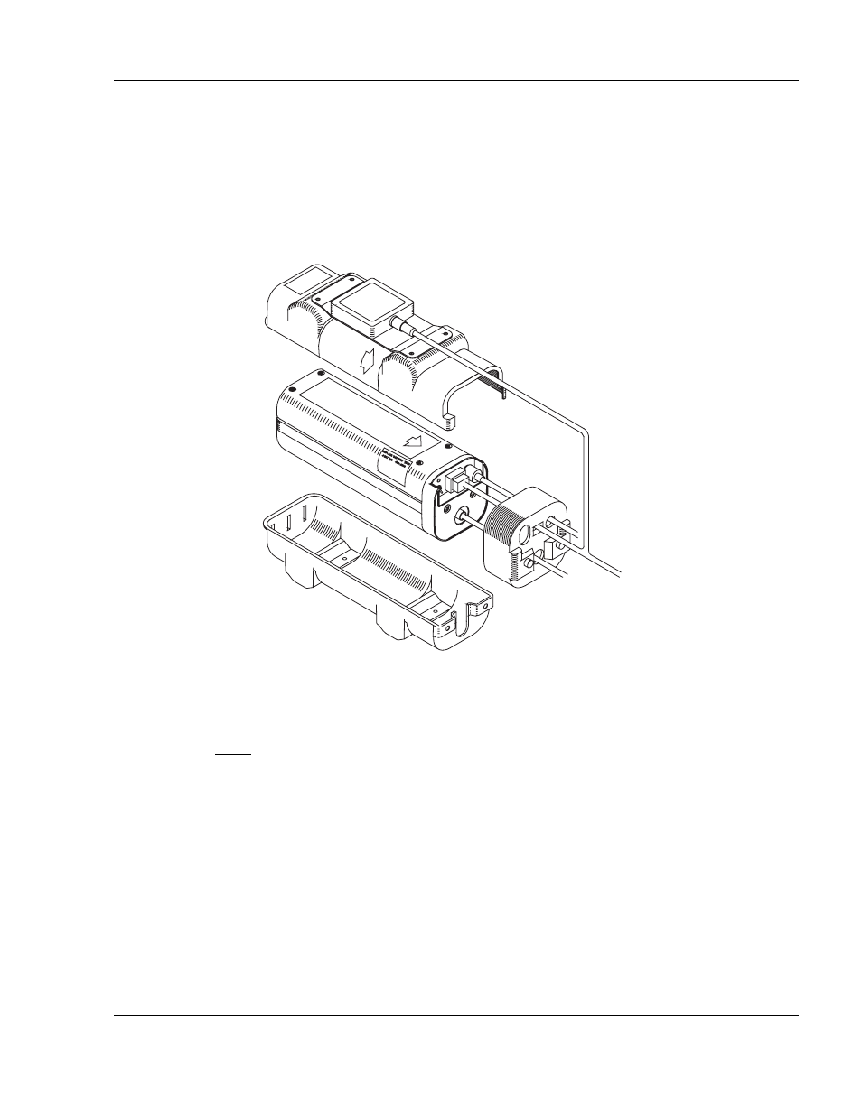
Figure 5. Dongle Wiring Harness Arrangement
(3)
A preassembled wire harness (P/N 611-4010) is provided with the Dongle.
NOTE: Disassembly of the 12 position rectangular connector is required when installing a
Dongle on an aircraft previously equipped with an ARTEX ELT to integrate the wire
harness. Refer to "Figure 6. Molex 12-Pin Connector Harness Arrangement", on
page 34. Use Molex extraction tool (Molex P/N 11-03-0002), or an equivalent tool for
0.062 in. terminal pins.
TO REMOTE
SWITCH
TO ANTENNA
(TYP.)