Pin assignment – Bosch ISP-EMIL-120 User Manual
Page 22
22
en |
ISP-EMIL-120 LSN Expansion Module
F.01U.076.548 | V3 | 2008.10
Installation manual
Bosch Sicherheitssysteme GmbH
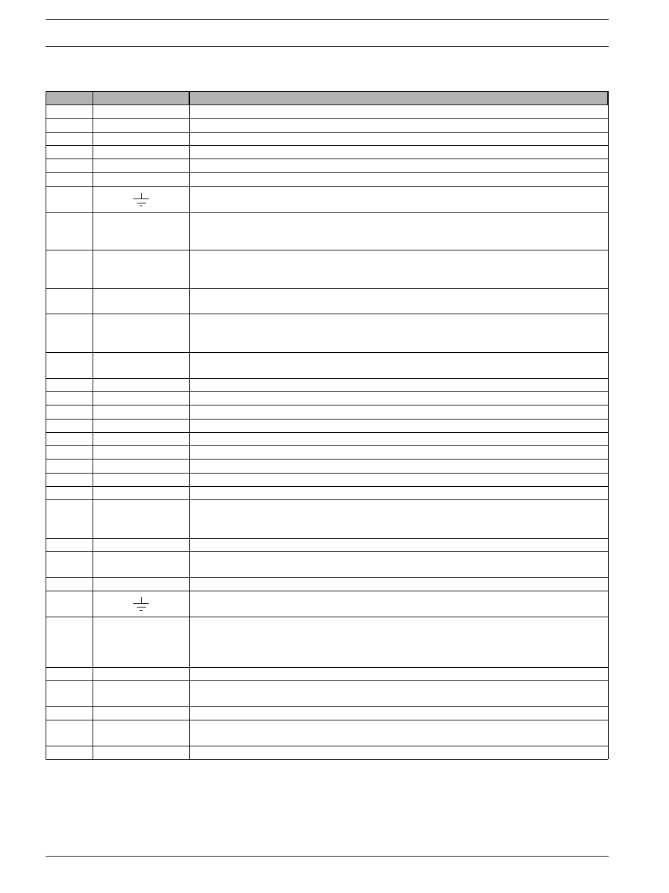
Pin assignment
No.
Connections
Features
1
+V
power supply 9.0 to 30 V, 1 and 5 connected internally
2
0 V
power supply 0 V, 2 and 6 connected internally
3/4
aLSN1/bLSN1
LSN incoming
5
+V
power supply 9.0 to 30 V, 5 and 1 connected internally
6
0 V
power supply 0 V, 6 and 2 connected internally
7/8
aLSN2/bLSN2
LSN outgoing
9/10
– Earth inputs for cable shield (if available), 9 and 10 connected internally
– Cable shield from NBS 10, (wire color: 10 = white/green and brown/green)
11/12
+12 V/0 V
Control output S1
+12 V/0 V switched minus potential, maximum output current 20 mA
– e.g. activation of relay module
– Block-type lock display LED1 "BLL" at NBS 10, (wire color: 11 = red, 12 = pink)
13/14
+12 V/0 V
Control output S2
+12 V/0 V switched minus potential, maximum output current 20 mA
– e.g. activation of relay module
– Block-type lock display LED2 "BLA" at NBS 10, (wire color: 13 = green, 14 = gray)
15/16
+12 V/0 V
Control output S3
+12 V/0 V switched minus potential, maximum output current 20 mA
e.g. activation of relay module
17/18
+12 V/0 V
Control output S4
+12 V/0 V switched minus potential, maximum output current 100 mA
– e.g. activation of relay module
– Block-type lock magnet "BSM" at NBS 10, (wire color: 17 = yellow, 18 = blue/red)
19/20
+12 V/0 V
Output
Power supply for external users, output current maximum 100 mA
21/22
SP
Free distributors for looping through, 21 and 22 connected internally
23/24
SP
Free distributors for looping through, 23 and 24 connected internally
25/26
SP
Free distributors for looping through, 25 and 26 connected internally
27/28
SP
Free distributors for looping through, 27 and 28 connected internally
29/30
SP
Free distributors for looping through, 29 and 30 connected internally
31/32
PL 1
Primary line for connection of detector zone 1
33/34
SP
e.g. connections for looping an external terminal resistance
35/36
PL 2
Primary line for connection of detector zone 2
37/38
SP
e.g. connections for looping an external terminal resistance
39/40
PL 3
– Primary line for connection of detector zone 3
– Block-type lock primary line at NBS 10, (wire color: 39 = black, 40 = blue)
– Coded arming device
41/42
SP
e.g. connections for looping an external terminal resistance
43/44
PL 4
– Primary line for connection of detector zone 4
– Coded arming device
45/46
SP
e.g. connections for looping an external terminal resistance
47/48
Earth inputs for cable shield (if available), 47 and 48 connected internally
49/50
PL 5
– Primary line for connection of detector zone 5 or
– Connection of line-fed glass break detectors
– Block-type lock tamper detector zone at NBS 10, (wire color: 49 = white,
50 = brown)
51/52
SP
e.g. connections for looping an external terminal resistance
53/54
PL 6
– Primary line for connection of detector zone 6
– Connection of line-fed glass break detectors
55/56
SP
e.g. connections for looping an external terminal resistance
57/58
WT
Connection of optional wall tamper contact. If the wall tamper contact
is not connected, the WT bridge (57 + 58) remains plugged in.
59/60
SP
Free distributors for looping through, 59 and 60 connected internally