Installation installation, 12 technical data, 13 fault finding – STIEBEL ELTRON DHF 12 - 24 C с 01.04.2007 User Manual
Page 22: The data on the unit rating plate are applicable), Table 3, Qualified installer, Table 4
22
|DHF C
www.stiebel-eltron.CoM
instAllAtion
instAllAtion
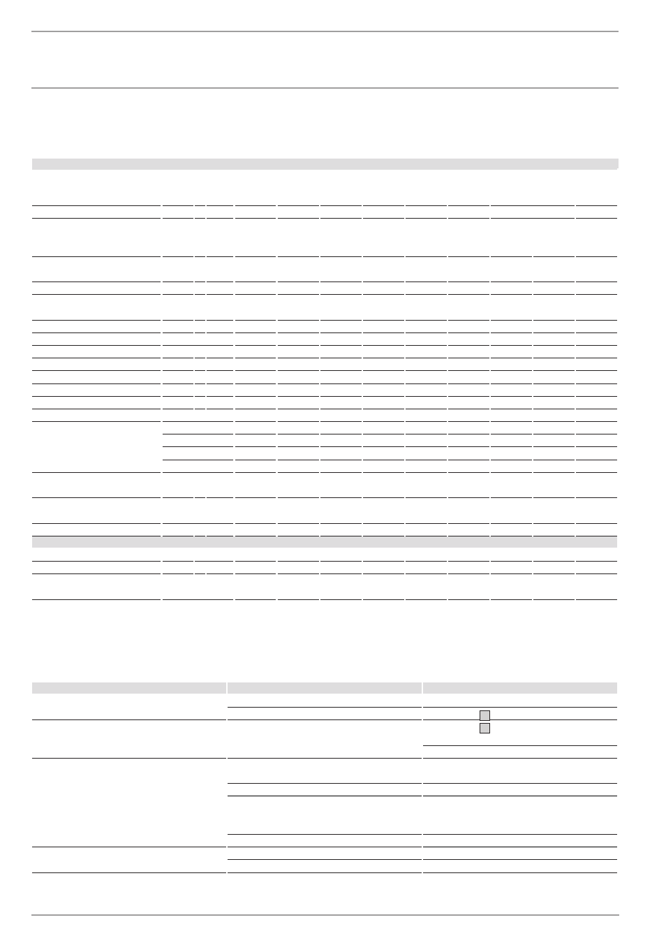
7.12 technical data
(the data on the unit rating plate are applicable)
Hydraulically controlled instantaneous water heaters
Type
DHF 13 C
compact
control
DHF 13 C-A
compact
control
DHF 15 C
compact
control
DHF 18 C
compact
control
DHF 21 C
compact
control
DHF 24 C
compact
control
DHF 12 C1
compact
control
DHF 13 C3
compact
control
Part no.
074301
222214
074302
074303
074304
074305
182137
185708
Rated voltage
Partial power
Rated power
Stage
Stage
•
••
V
kW
kW
400
6.6
13.2
400
6.6
13.2
400
7.5
15
400
9
18
400
10.5
21
400
12
24
220
8
12
230
8.8
13.2
230
6.6
13.2
Min. flow rate to activate
Stage
Stage
•
••
l/min
l/min
2.5
3.7
3.0
4.5
3.0
4.5
3.9
5.9
4.4
6.4
4.9
7.6
2.5
3.7
2.5
3.7
2.5
3.7
Flow rate limiter
l/min
4.5
6.5
6.5
7.0
7.5
8.0
4.5
4.5
4.5
Pressure loss*
Flow rate
MPa
l/min
0.05
3.7
0.055
4.5
0.055
4.5
0.06
5.9
0.06
6.4
0.07
7.6
0.05
3.7
0.05
3.7
0.05
3.7
Nominal water volume
l
0.6
0.6
0.6
0.6
0.6
0.6
0.6
0.6
0.6
Type of construction
closed
x
x
x
x
x
x
x
x
x
Rated overpressure
MPa
1
1
1
1
1
1
1
1
1
Weight
kg
4.0
4.0
4.0
4.0
4.0
4.0
4.0
4.0
4.0
Protection class to EN 60335
1
1
1
1
1
1
1
1
1
Protection mode to EN 60529
IP 24
IP 24
IP 24
IP 24
IP 24
IP 24
IP 24
IP 24
IP 24
Test mark, see unit rating plate
x
x
x
x
x
x
x
x
x
Water connection
external thread
G ½
G ½
G ½
G ½
G ½
G ½
G ½
G ½
G ½
Electrical connection
3/PE ~ 400 V
x
x
x
x
x
x
1/N/PE ~ 220 V
x
1/N/PE ~ 230 V
x
3/PE ~ 230 V
x
Max. mains impedance Z max to
EN 61000-3-11
Ω
-
-
-
-
-
0.44
0.15
0.14
0.45
Heating element
Copper tubular
heating elementr
x
x
x
x
x
x
x
x
x
Cold water inlet
°C
≤ 20
≤ 30
≤ 20
≤ 20
≤ 20
≤ 20
≤ 20
≤ 20
≤ 20
use in waters
Total alkaline earths
mol/m³
≤ 2.5
≤ 2.5
≤ 2.5
≤ 2.5
≤ 2.5
≤ 2.5
≤ 2.5
≤ 2.5
≤ 2.5
Overall hardness (earlier unit)
°d
≤ 14
≤ 14
≤ 14
≤ 14
≤ 14
≤ 14
≤ 14
≤ 14
≤ 14
Hardness range (earlier unit)
Inclusive of 2 (me-
dium hard)
x
x
x
x
x
x
x
x
x
Table 3
* Pressure drop values also apply to the minimum flow pressure in accordance with DIN 44851 / Flow rate for heating from 10 °C to 55 °C
(∆-ϑ 45 K). A pressure drop of 0.1 MPa (1 bar) is recommended for pipe network dimensioning, in line with DIN 1988 Part 3, Table 4.
7.13 Fault finding
- qualified installer
Cause
Cause
» remedy
Unit does not switch on.
Water pressure in cold water pipe too low.
Descale or replace showerhead/Perlator®.
Strainer in 3-way valve (
6) fouled.
Clean strainer (
d
, 22).
Differential pressure switch (
10, control valve MRC)
with flow rate controller does not switch on in spite
of the hot water tap being turned fully on.
Necessary switch-on quantity to switch on the hea-
ting output is not reached.
Clean strainer (
d
, 22).
Check water pressure.
Unit does not produce hot water in spite of an audible
switch-on noise by the differential pressure switch.
Safety temperature limiter (
12) has tripped, possibly
due to:
Intlet temperature too high.
Check intlet temperature.
Control valve (MRC) faulty
.
Check and if necessary replace control valve.
Rinse
heating-system of unit, in order to avoid over-hea-
ting.
Press reset button
(
13).
Element scaled up
.
De-scale or replace element.
Heating system does not heat water.
No voltage.
Check fuse (house installation).
Heating system faulty.
Replace tubular heating element heating system (
11).
Table 4