Applicable literature, Specifications, Inputs – Schneider Electric MS40-717X User Manual
Page 2: Control signal, Power input, Impedance, Connections, Class 1 power, Class 2 power & control, Ground
2
© Copyright 2010 Schneider Electric All Rights Reserved.
F-26748-6
Applicable Literature
SPECIFICATIONS
Inputs
Control Signal: 4 to 20 mAdc (with the addition of a 500 Ohm resistor - not included) or 2
to 10 Vdc. See Figure-1 through Figure-8.
Power Input: See Table-1. All 24 Vac and 22-30 Vdc circuits are Class 2. All circuits 30 Vac
and above are Class 1.
Impedance: 2 to 10 Vdc, 121k
Ω. 4 to 20 mAdc, 500Ω. (user supplied).
Connections:
Class 1 Power, 24 inch (61 cm) long, 18 AWG color coded pigtail leads.
Class 2 Power & Control, 36 inch (91 cm) long, 22 AWG color coded appliance cable
leads.
Ground, 36 inch (91 cm) long, 18 AWG green/yellow pigtail lead.
Outputs
Electrical:
Position Feedback Voltage, “AO” 2 to 10 Vdc (max. 0.5 ma) output signal for position
feedback or to operate up to four additional slave actuators.
Stroke, Electronically limited to 92° ±1°.
Action, Direct acting, 0° position with 4 mAdc or 2 Vdc input.
Torque See Table-1.
Duty Cycle 100%.
Timing See Table-1.
Mechanical:
Anti-Rotation Bracket,
Standard 9" long x 13/16" wide (229 x 21 mm), included with the actuator.
Optional Order AM-752 (4" long x 1-11/16" wide) for mounting the actuator in narrow
spaces.
Universal Mounting Clamps, Two clamps are required for all mounting configurations.
Standard 3/8" to 1/2" (10 to 13 mm) round and square shaft mounting clamps are
included with the actuator.
Optional Order AM-753 for 5/8" (16 mm) square and 3/4" to 1" (19 to 25 mm) round
damper shafts, two per package.
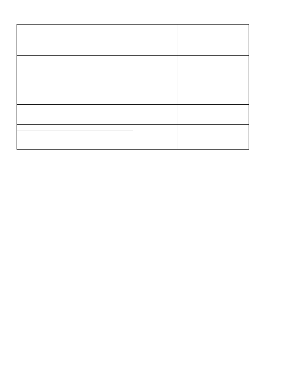
F-Number
Description
Audience
Purpose
F-26750
MX40-6XXX-2XX, MX40-7XXX-2XX Series
Actuator/Linkage Assemblies General Instructions
– Sales Personnel
– Application Engineers
– Installers
– Service Personnel
– Start-up Technicians
Describes the globe valve
actuator/linkage assembly’s features,
specifications, and possible applications.
Provides step-by-step mounting
instructions.
F-26646
MX40-7XXX, MX40-6XXX Series DuraDrive Actuator
Selection Guide
– Sales Personnel
– Application Engineers
– Installers
– Service Personnel
– Start-up Technicians
Provides actuator specifications and part
number cross referencing of phased out
actuators with the new direct-coupled
actuators.
F-26752
VX-2000, VX-7000 Series
MX40-7XXX, MX40-6XXX Series
Ball/Linked Globe Valve Assemblies
Actuator/Linkage Assemblies Selection Guide
– Sales Personnel
– Application Engineers
– Installers
– Service Personnel
– Start-up Technicians
Provides part number cross referencing of
phased out actuators with the new direct-
coupled actuators.
F-26080
EN-205 Water System Guidelines
– Application Engineers
– Installers
– Service Personnel
– Start-up Technicians
Describes Schneider Electric approved
water treatment practices.
F-13755
CA-28 Control Valve Sizing
– Application Engineers
– Installers
– Service Personnel
– Start-up Technicians
Provides charts, equations, and diagrams
to assist in the configuration of valve
system applications. TOOL-150, valve
sizing slide rule may be purchased
separately.
F-11080
Valve Selection Chart Water
F-11366
Valve Selection Chart Steam (two-way valves only)