Inverter control panel – Xantrex Technology PH1800 User Manual
Page 26
Operation
2–2
975-0288-01-01
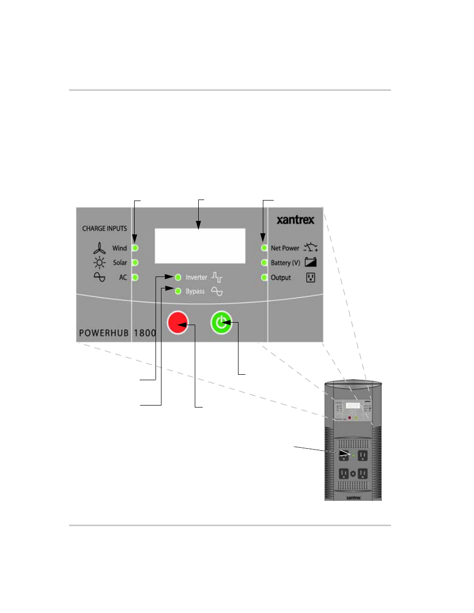
Inverter Control Panel
The Inverter Control Panel has nine LEDs; six Status LEDs (three for
input/charge levels and three for output power levels), two Mode
Indication LEDs, one AC Indicator LED. Two push buttons provide
ON/OFF control and Display Select features. An LED Display
communicates input and output power levels, battery voltage, and error
codes.
Figure 2-1 The PowerHub 1800 Inverter Control Panel
AC Indicator
LED
Select Button
On/Off Power
Button*
LED Display
Input LEDs
8.
8.
8.
8.
Output LEDs
Inverter Mode
Indicator LED
Bypass Mode
Indicator LED
Important:
*The On/Off Power Button only activates or
deactivates power to the Inverter/charger and display.
If the PowerHub is connected to any AC power
source it will pass that power through to the outlets
on the front panel and to the output terminals.