Controls and functions / connections, Top panel rear panel – Zoom G2 User Manual
Page 4
ZOOM G2
6
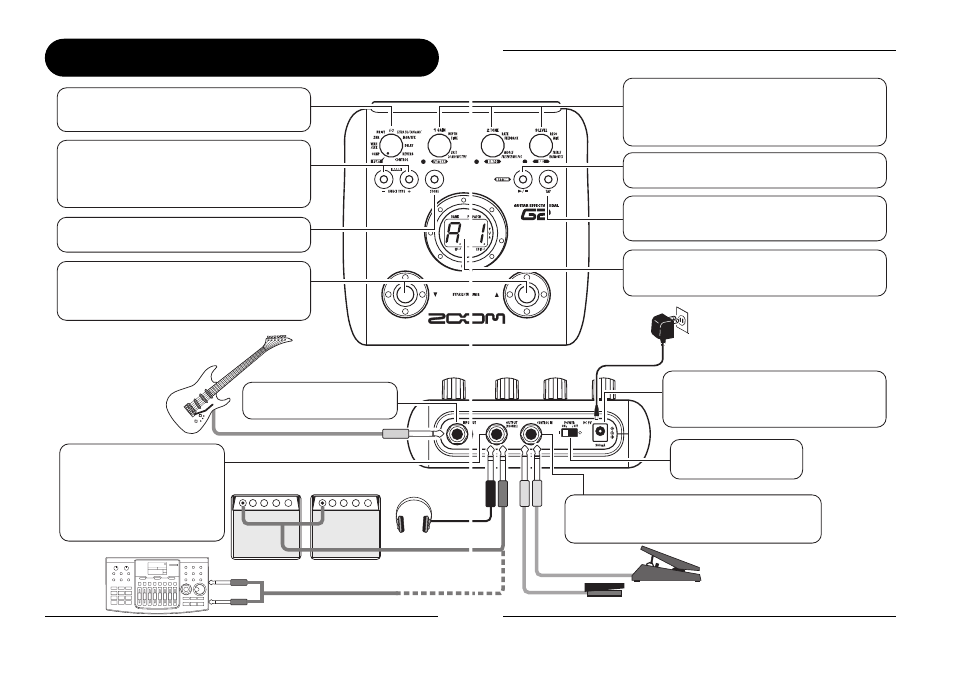
Controls and Functions / Connections
Module selector
Top Panel
Rear Panel
Switches between play mode and edit mode. In edit
mode, the knob selects the module for operation.
[
W]/[Q] foot switches
These switches are used for selecting patches,
switching effect modules on and off, controlling the
tuner, and other functions.
[STORE] key
Serves for storing edited patches in memory.
[OUTPUT/PHONES] jack
Guitar
MTR (multitrack recorder)
Guitar amplifiers
Headphones
This stereo phone jack serves for
connection to a guitar amplifier or
recorder. It is also possible to use a
Y cable for sending the output to
two amplifiers, or to plug a pair of
stereo headphones into this jack.
[INPUT] jack
Serves for connecting the guitar.
BANK [-]/[+] keys
In play mode, the keys serve for directly switching to
the next lower or higher bank.
In edit mode, the keys switch the effect type for the
currently selected module.
Controls and Functions / Connections
ZOOM G2
7
Parameter knobs 1 - 3
These knobs allow changing the level of effect
parameters or of the overall patch. During rhythm
playback, the knobs let you select a pattern, set the
tempo, and adjust the rhythm volume.
[TAP] key
Allows manual input of time related effect parameter
values such as delay time, and rhythm pattern tempo.
Display
Shows patch numbers, setting values, and other
information about operating the G2.
[CONTROL IN] jack
Serves for connection of the optional foot switch
(FS01) or expression pedal (FP01/FP02).
[DC IN] jack
An AC adapter (ZOOM AD-0006) with a rated
output of 9 volts DC, 300 mA (center minus
plug) can be plugged into this jack.
[POWER] switch
Turns the unit on and off.
RHYTHM [
R/P] key
Serves to start/stop rhythm playback.
AC adapter
FP01/FP02
FS01