Wolf Appliance Company Drawer Microwave User Manual
Page 7
7
I N S TA L L AT I O N
I N S T R U C T I O N S
3 0 " ( 7 6 2 )
D R A W E R
M I C R OWAV E
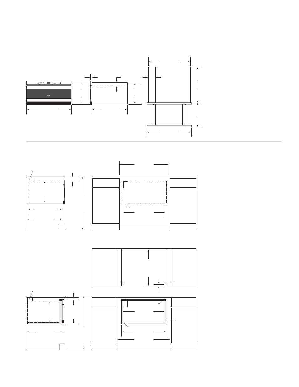
O V E R A L L D I M E N S I O N S
I N S T A L L A T I O N S P E C I F I C A T I O N S
Standard Installation
Flush Inset Installation
28
3
/
8
"
(721)
OPENING WIDTH
23
1
/
2
"
min (597)
OPENING DEPTH
33"
rec (838)
30"
min (762)
CABINET WIDTH
36"
(914)
STANDARD
FLOOR TO
COUNTERTOP
HEIGHT
2"
(51)
24"
min (610)
CABINET DEPTH
3
1
/
2
"
(89) x
2"
(51)
ANTI-TIP BLOCK
14
3
/
4
"
(375)
OPENING
HEIGHT
Dashed lines represent profile of unit.
FRONT VIEW
SIDE VIEW
5
/
8
"
(16) PLATFORM
E
36"
rec (914)
33"
min (838)
CABINET WIDTH
30
3
/
8
"
(772)
FLUSH INSET WIDTH
28
3
/
8
"
(721)
OPENING WIDTH
E
1"
(25)
SIDE CLEATS
3
/
8
"
(10) PLATFORM
5
/
8
"
(16) TOP CLEAT
SIDE CLEATS
24
3
/
4
"
min
(629)
FLUSH
INSET
DEPTH
1
1
/
4
"
(32)
36"
(914)
STANDARD
FLOOR TO
COUNTERTOP
HEIGHT
1
9
/
16
"
(38)
25"
min (635)
CABINET DEPTH
14
3
/
4
"
(375)
OPENING
HEIGHT
15
3
/
4
"
(400)
FLUSH INSET
HEIGHT
3
1
/
2
"
(89) x
2"
(51)
ANTI-TIP BLOCK
Dashed line represents profile of unit.
FRONT VIEW
SIDE VIEW
TOP VIEW
23
3
/
8
"
(594)
BEHIND FRAME
15
1
/
4
"
(387)
29
7
/
8
"
(759)
28
1
/
8
"
(714)
POWER
CORD
CHANNEL
1
1
/
4
"
(32)
4
11
/
16
"
(119)
2"
(51)
14
9
/
16
"
(370)
23
3
/
8
"
(594)
16
1
/
2
"
(419)
29
7
/
8
"
(759)
The drawer microwave
can also be installed
using an electrical
outlet in an adjacent
cabinet within the area
where the provided
electrical cord can
reach. Power cord
access hole in cabinet
should be a minimum
1
1
/
2
" (38) diameter
hole and deburred of
all sharp edges.
IMPORTANT NOTE:
Always allow sufficient
power cord length to
the electrical outlet to
prevent tension.
Always check electrical
codes for requirements.