Work setup, Blade break-in procedures, Securing the workpiece for square cuts – Wilton 7020/7040 User Manual
Page 9: Adjusting the vise for angle cuts
10
A minimum of three teeth should be on the work
piece at all times for proper cutting. The blade and
workpiece can be damaged if the teeth are so far apart
that they straddle the workpiece.
For very high production on cutting of special mate-
rials, or to cut hard-to-cut materials such as stainless
steel, tool steel, or titanium, you can ask your industrial
distributor for more specific blade recommendations.
Also, the supplier who provides the workpiece material
should be prepared to provide you with very specific
instructions regarding the best blade (and coolant or
cutting fluid, if needed) for the material and shape sup-
plied.
Blade Break-in Procedures
New blades are very sharp and, therefore, have a
tooth geometry which is easily damaged if a careful
break-in procedure is not followed. Consult the blade
manufacturer’s literature for break-in of specific blades
on specific materials. However, the following proce-
dure will be adequate for break-in of Wilton-supplied
blades on lower alloy ferrous materials.
1. Clamp a round section workpiece in the vise. The
workpiece should be 2 inches or larger in diameter.
2. Set the saw on low speed. Start the cut with a very
light feed rate.
3. When the saw has completed 1/3 of the cut, in-
crease the feed rate slightly and allow the saw to
complete the cut.
4. Keep the same hydraulic cylinder setting and begin
a second cut on the same or similar workpiece.
5. When the blade has completed about 1/3 of the cut,
increase the feed rate. Watch the chip formation
until cutting is at its most efficient rate and allow the
saw to complete the cut (see Evaluating Blade Effi-
ciency). The blade is now considered ready for
regular service.
Work Setup
Securing the Workpiece for
Square Cuts
1. Raise the saw head (refer to Figure 5).
2. Slide the left vise jaw far enough to the left to allow
the workpiece to be placed in the vise.
3. Place the workpiece on the work table. If the
workpiece is long, provide support at the other end.
It may also be necessary to provide additional down-
ward clamping to hold the workpiece securely on
the work table.
4. Turn clamping hand wheel clockwise to clamp the
workpiece in position against the fixed (right) vise
jaw.
5. After completing the cut, turn the clamping hand
wheel counterclockwise and slide the left jaw away
from the workpiece.
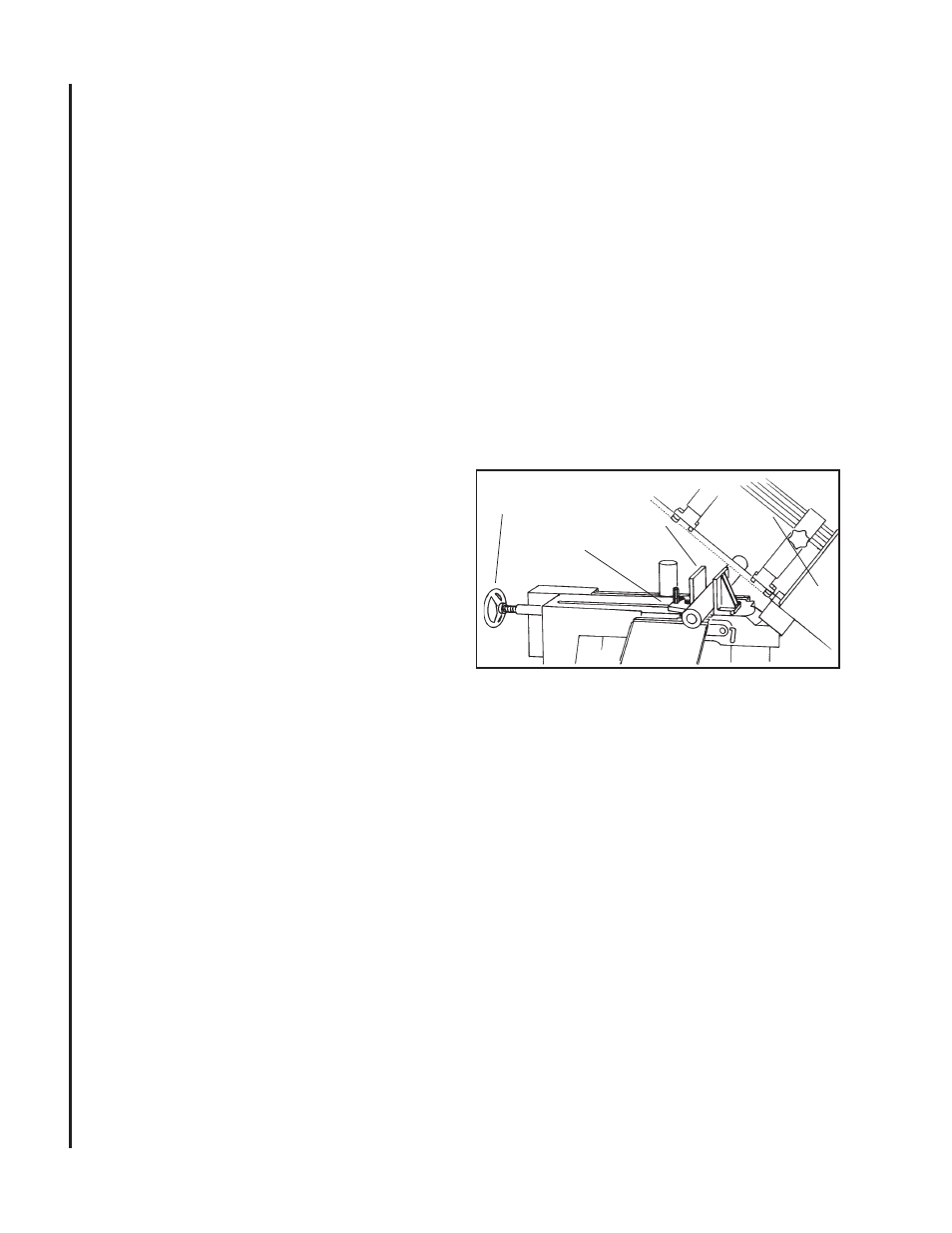
Figure 5: Securing workpiece
Adjusting the Vise for Angle
Cuts
1. Referring to Figure 5, loosen the angle locking screw
and the pivot screw on the left vise jaw.
2. Turn the locking handle on the round, angle-setting
block counterclockwise to unlock the block. Slide
the block until the pointer on the block is aligned
with desired angle (see figure 7). Tighten the lock-
ing handle to set the angle.
3. Set the workpiece in the vise. Put the front end of
the workpiece against the corner of the right vise
jaw. Put the rear end of the workpiece against the
angle-setting block.
4. Turn clamping hand wheel clockwise until the left
vise jaw is parallel with the workpiece. Tighten the
pivot screw and angle locking screw on the left vise
jaw. Clamp the workpiece in position.
5. After completing the cut, turn the clamping hand
wheel counterclockwise and slide the left jaw away
from the workpiece.
Clamping
Hand
Wheel
Work Table
Left Vise Jaw
Saw Head