Blade guide bearing adjustment, Drive belt tension adjustment – Wilton 7015 User Manual
Page 16
16
Blade Guide Bearing Adjustment
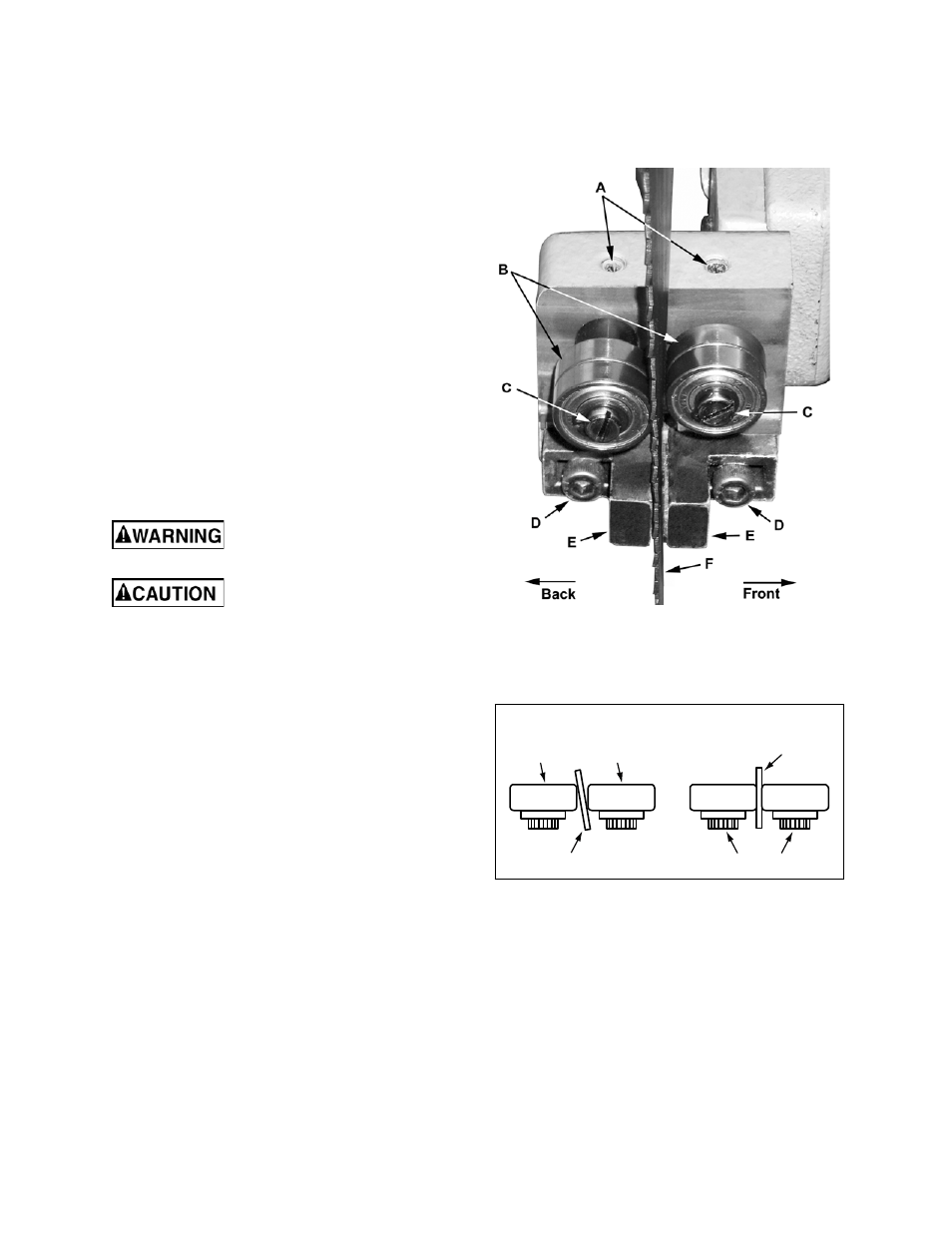
Referring to Figure 16:
Guide bearings and guide inserts are located on
either side of the saw blade and provide stability for
the blade when the saw is in operation. These
bearings rotate on an eccentric shaft so the distance
from the blade can be adjusted for optimal
performance.
Blade guides provide blade support.
Guide bearings and blade guides are initially
adjusted at the factory and should rarely require
adjustment
It is always better to try a new blade when cutting
performance is poor. If performance remains poor
after changing the blade, check the blade guides for
proper spacing. For most efficient operation and
maximum accuracy, clearance between the blade
and the guide bearings should be 0.001-inch. The
bearings will still turn freely with this clearance. If the
clearance is incorrect, the blade may track off the
drive wheel.
Disconnect the cut-off saw from
its electrical power source.
Check the blade to make sure
the welded section is the same thickness as the
rest of the blade. If the blade is thicker at the
weld, the guide bearings may be damaged.
If required, adjust first one guide bearing and blade
guide assembly then the other as follows:
1. Using a 3mm hex wrench, loosen two set screws
(A) securing the eccentric bushings.
2. Using a 5mm hex wrench, loosen two socket
head cap screws (D) securing the carbide blade
guides (E).
3. Position
the
bearings (B) by turning the bushings
(C) with a flat-head screwdriver. Set the
clearance between the bearings (B) and blade
(F) at approximately 0.001 inch.
When properly adjusted, the blade should be in
a vertical position between the bearings as
shown in Figure 17.
4. Tighten
the
set screws (A).
5. Adjust
the
blade guides (E) so they support the
blade without pinching and tighten the socket
head cap screws.
6. When the adjustment is correct, the guide
bearings should rotate freely with slight pressure
of the finger (blade stopped).
Figure 16
Outer
Roller
Inner
Roller
Locking Screw
INCORRECT
CORRECT
Saw Blade
Saw Blade
Figure 17
Drive Belt Tension Adjustment
The
V-belt will stretch with use and may
occasionally require tension adjustment. To adjust
see the Changing Drive Belt section (page 19)
steps 1, 2, 6, and 7.