24 dealer service – Woods Equipment RD6000-2 User Manual
Page 26
24 Dealer Service
MAN0180 (Rev. 1/7/2005)
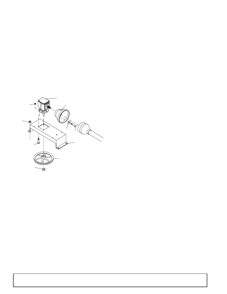
Remove Gearbox from Mower
Refer to Figure 22.
1. Disconnect and remove the rear driveline from the
gearbox.
2. Remove vent plug and siphon gear lube from
housing through this opening.
3. Remove gearbox stand (20) from mower deck by
removing four flanged lock nuts (56).
4. Remove four cap screws (43) and washers (42)
and remove shield (22) from gearbox.
5. Remove castle nut and hardware from output shaft
of gearbox.
6. Remove sheave (19) from gearbox.
7. Remove four bolts (63) that attach gearbox to
gearbox stand and remove gearbox.
Figure 22. Gearbox Stand Assembly
Disassemble Gearbox
1. Remove top cover (22) from housing. Turn gearbox
upside down and pour out remaining gear oil from
gearbox.
2. Remove oil cap (20) (to be replaced).
3. Remove snap ring (10) and shim (13) from input
shaft (3).
4. Support gearbox in hand press and push on input
shaft (3) to remove bearing (7).
5. Remove gear (1) from inside housing.
6. Remove oil seal (19) from front of housing (to be
replaced).
7. Remove snap ring (10) and shim (13) from front of
housing (2).
8. Remove input bearing (7) by using a punch and
hammer from outside of housing.
9. Support housing in vise in a horizontal position.
10. The castle nut (15) and cotter pin (25) are already
removed with the drive sheave. Remove the snap
ring (21), washer (8), and seal (18).
11. Remove cotter pin (9), castle nut (14), and washer
(17) from output shaft (4).
12. Remove output shaft (4) by using a punch and
hammer and tap on top to drive down.
13. Remove gear (5) and shim (16) from inside
housing.
14. Remove bearing (26) by using a punch and
hammer from the top, outside the housing.
15. Support housing upside down (top cover surface)
and remove bearing (6) by using a punch and
hammer from the bottom side of the housing.
16. Inspect gears for broken teeth and wear. Some
wear is normal and will show on loaded side.
Forged gear surfaces are rough when new. Check
that wear pattern is smooth.
17. Inspect vertical and horizontal shafts for grooves,
nicks, or bumps in the areas where the seals seat.
Resurface any damage with emery cloth.
18. Inspect housing and caps for cracks or other
damage.
Reassemble Gearbox
Refer to Figure 23
NOTE: Repair to this gearbox is limited to replacing
bearings, seals, and gaskets. Replacing gears, shafts,
and a housing is not cost effective. Purchasing a com-
plete gearbox is more economical.
1. Clean housing, paying specific attention to areas
where gaskets will be installed.
2. Wash housing and all components thoroughly.
Select a clean area for gearbox assembly. Replace
all seals, bearings, and gaskets. All parts must be
clean and lightly oiled before reassembling.
3. Insert output bearings (6 & 26) in the housing,
using a round tube of the correct diameter and a
hand press.
4. Slide output shaft (4) through both bearings (6 &
26) until it rests against bearing (6).
5. Slide shim (16) over output shaft (4).
56
59
22
42
43
63
19
CD4986A-1
Vent Plug
20
Castle Nut
19. Sheave, offset 12.4 PD
20. Gearbox stand
22. Shield, counter cone
42. Washer, flat standard 5/16
43. Screw, HHCS 8mm x 1.25P x 16mm
56. Nut, flanged lock 1/2 NC
59. Nut, flanged lock 5/8 NC
63. Screw, Flanged Hex Head 5/8 NC x 1-3/4