Vinotemp WINE-MATE VINO-2500SSW User Manual
Page 19
- 18 -
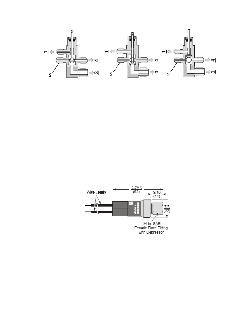
BACK POSITION FRONT POSITION MIDDLE POSITION
Fig. 8 Base Valve Operation
4. Temperature Controller and Air Probe
1) The air probe shall be located in the wine cellar 5 ft above the floor or the air
return area, but it shall not be located in the air supply area or other areas
where air is not circulated.
2) Air probe can be pulled out of the temperature controller around 5 ft; if
additional wires are needed, 18 gauge wires may be used to extend the air
probe.
5.
Checking Control Settings
1) Use of the
encapsulated pressure control (if applicable)
Fixed suction pressure setting: Cut in = 32 psig; Cut out = 10 psig
Fig. 9 Fixed Pressure Control
2)
Low ambient condition kit (if applicable)
A.
Use of the crankcase heater
The crankcase heater is installed around the lower part of the compressor and
shall be turned on all the time. The heater is self-regulated.