Venting installation, Continued – Vanguard Heating VDDVF36STN/STP User Manual
Page 10
10
106918
DIRECT-VENT GAS FIREPLACE
VDDVF36PN/PP and VDDVF36STN/STP Series
®
VENTING
INSTALLATION
Continued
UP
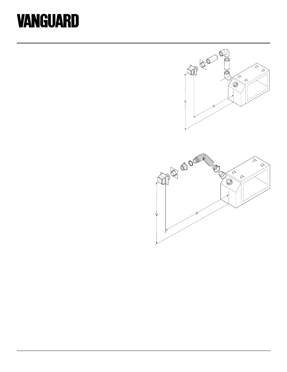
Figure 21 - Horizontal Termination Configuration for Rigid Venting Using One
90
°
Elbow
Figure 22 - Horizontal Termination Using Flexible Venting
Horizontal Venting
Vertical (V)
Horizontal (H)
49.5" min.
15" max.
(45
°
elbow, 1' vertical pipe, 90
°
elbow)
61.5" min.
34" max.
73.5" min.
58" max.
85.5" min.
10' max.
102.5" min.
20' max.
UP
Horizontal Venting
See information in
Figure 21 for
Vertical(V) and
Horizontal(H) maxi-
mums and minimums.
The same amounts
apply for flexible
venting.
FGFVK Vent Kit Shown
Horizontal Termination
Configurations
Figures 21 through 23 show different con-
figurations for venting with horizontal ter-
mination. Each figure includes a chart with
vertical minimum/maximum and horizon-
tal maximum dimensions which must be
met. All connections must be sealed with
high temperature silicone sealant as speci-
fied in the second warning statement on
page 7. All horizontal terminations require
1/4" rise per 12" of horizontal run.
Note: The 30
°
Starter
Elbow Must Be
Discarded and
Replaced with a 45
°
Starter Elbow.
45
°
Starter
Elbow
Required