Rs-232 controller connection, Figure 3-16 . rs-232 control system connection, 16. rs-232 control system connection – Vidikron Vision v120 User Manual
Page 49: Pre l iminar y
Vidikron Vision Model 120 Owner’s Operating Manual
37
PRE
L
IMINAR
Y
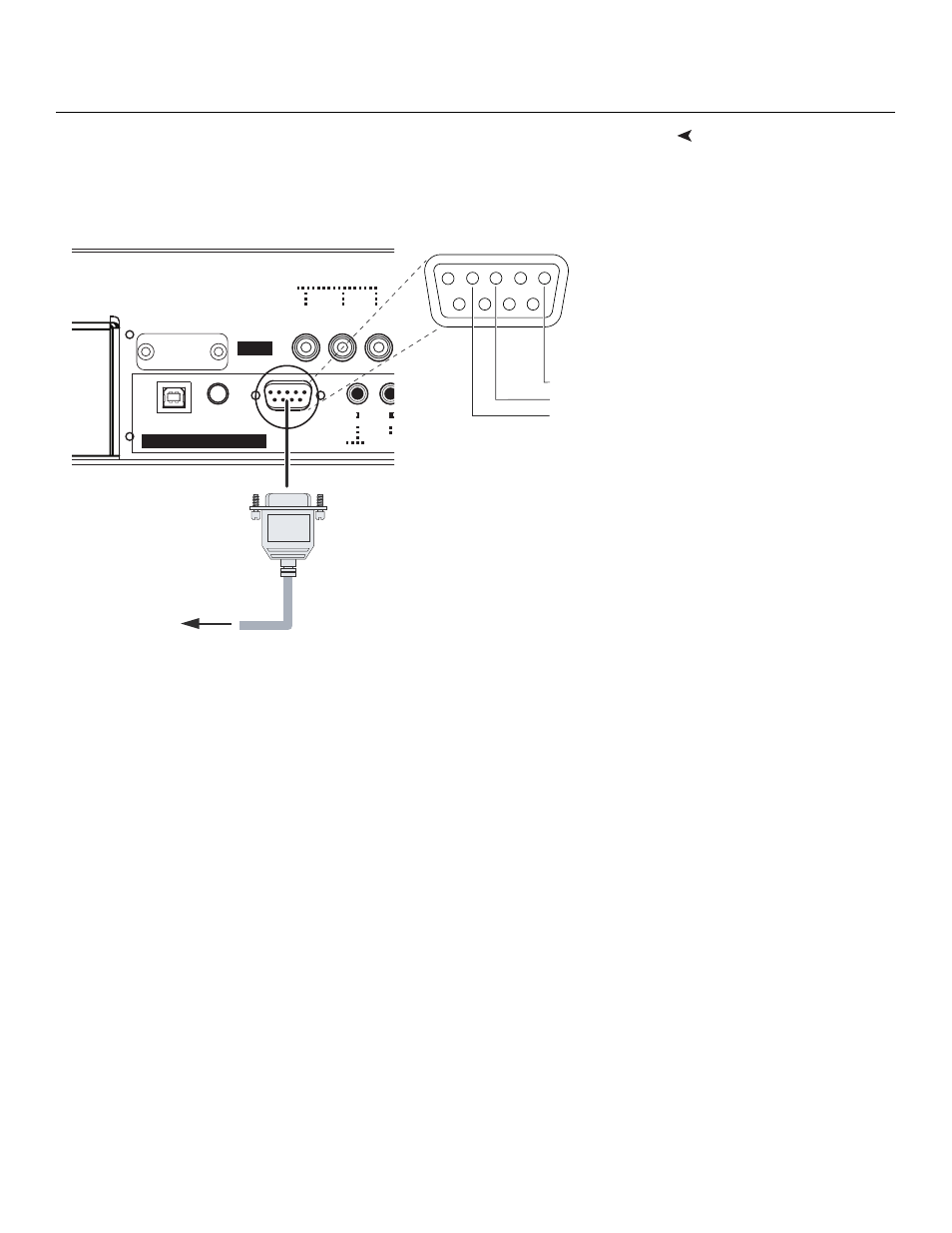
RS-232 Controller
Connection
Use a “null-modem” 9-pin RS-232 cable to connect a PC or home theater control/automation
system (if present) to the RS-232/485 port on the VHD Controller; see Figure 3-16.
For more information about using this connection, refer to Serial Communications on
page 67.
Figure 3-16. RS-232 Control System Connection
II
I
TRIGG
RS-232 / 485
WIRED
REMOTE
SERVICE ONLY
SYSTEM CONTROL INTERFACE
HD1
Y / G
Pr / R
Pb / B
INPUTS
Service port.
Not for user
access
1
2
3
4
5
7
8
9
6
to Automation/
Control System
or PC
5 Ground
3 Transmit Data
2 Receive Data
(none of the other pins are used)