Install the unit – Venmar HEPA 3100* User Manual
Page 14
5.4 I
NSTALLING
N
ON
-I
NSULATED
D
UCTS AND
R
EGISTERS
(
CONT
’
D
)
5.4.2 C
ENTRAL DRAW
P
OINT
(
AS ILLUSTRATED IN
S
ECTION
1.1.2) (
CONT
’
D
)
Fresh/Filtered air ductwork (Return side connection) (cont’d)
HEPA 3100, HF 3.1
AND
HEPA 4100
UNITS ONLY
(
CONT
’
D
)
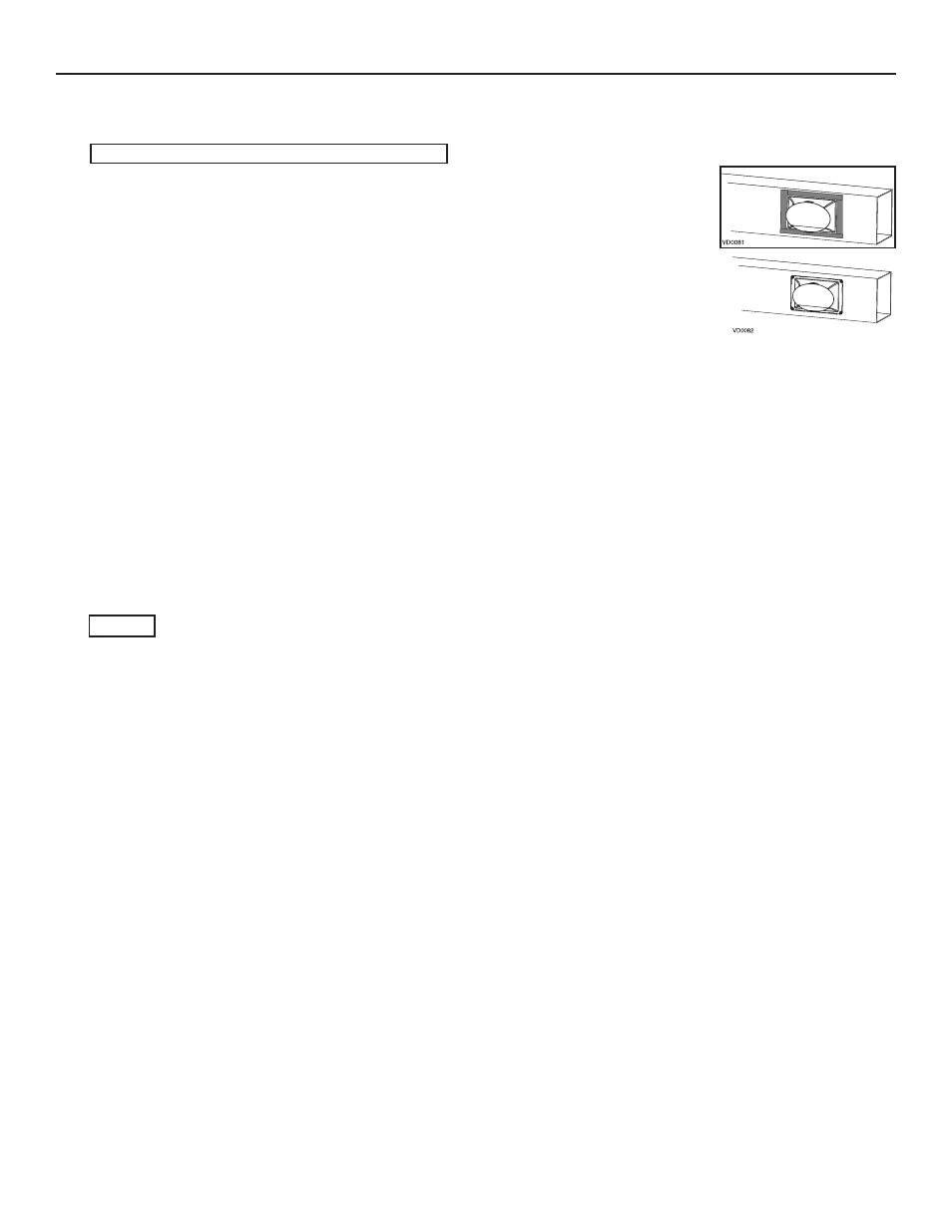
• Fix the duct connector to the forced air unit duct using its 4 retaining screws (#8 x 3/4” long). Seal
with duct tape.
• Take one end of the 8’’ flexible duct and slide it over the duct connector. Secure with a tie wrap.
Carefully seal the connection with duct tape. Identifiy the duct using the blue sticker dot included.
• Attach this duct to the
FRESH AIR TO BUILDING
port (see icon on the top of the unit), using tie wrap and
duct tape.
5.4.3 R
ETURN
-
TO
-R
ETURN
(
AS ILLUSTRATED IN
S
ECTIONS
1.1.3
AND
1.2.2)
Fresh/Filtered air ductwork (Return side connection)
Same as for Central Draw Point, described in point 5.4.2.
Stale air ductwork (Return side connection)
A
LL UNITS
• Locate the stale air ductwork opening at least 3’ (0.9 m) from the fresh/filtered air ductwork
connection. For the HRV 2600 and HR 2.6 units, use a steel transition (not provided, available
in hardware stores). Proceed as for the fresh/filtered air ductwork, but instead of using the blue
dot sticker to identify the duct, use the red dot. (No dots for HRV 2600 and HR 2.6 units.)
• Attach this duct to the
EXHAUST AIR FROM BUILDING
port (see icon on the top of the unit), using tie wrap
and duct tape.
5. INSTALL THE UNIT
(CONT’D)