Rs-232 controller connection, Figure 3-11 . rs-232 control system connection, Figure 3-12 . connecting 12-volt trigger outputs – Vidikron 90 User Manual
Page 34: Connecting to ac power, Rs-232 controller connection -14, Connecting to ac power -14, 11. rs-232 control system connection -14, 12. connecting 12-volt trigger outputs -14, 2 transmit data 3 receive data 5 ground
Vidikron Vision Model 90 Owner’s Operating Manual
RS-232 Controller
Connection
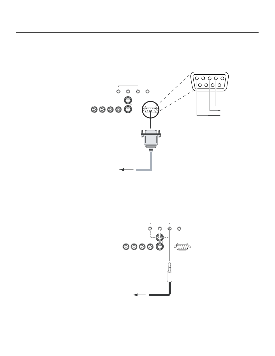
Use a standard, 9-pin RS-232 cable to connect a PC or home theater control/automation
system (if present) to the RS-232 CONTROL port on the Vision 90; see Figure 3-11.
For more information about using this connection, refer to Serial Communications on
page 6-1.
Figure 3-11. RS-232 Control System Connection
Connecting 12-Volt Trigger
Outputs to External Theater
Components
If your home theater contains other devices that respond to 12-volt triggers (such as
retractable screens or screen masks), connect them to the 12-volt trigger outputs as shown in
Figure 3-12.
Figure 3-12. Connecting 12-Volt Trigger Outputs
Connecting to AC Power
Plug the female end of the power cord into the AC receptacle on the rear of the Vision 90 (AC
100V ~ 240V). Then, connect the other end to your AC power source.
➤
COMPONENT VIDEO
Pb
Pr
Y
COMPONENT VIDEO
Y
Pr
Pb
VIDEO
VIDEO
S-VIDEO 2
S-VIDEO 2
S-VIDEO 1
S-VIDEO 1
RS-232
CONTROL
RS-232
CONTROL
IR
IR
1
2
3
1
2
3
TRIGGERS
TRIGGERS
1
2
3
4
5
7
8
9
6
to Automation/
Control System
or PC
2 Transmit Data
3 Receive Data
5 Ground
(none of the other pins are used)
➤
COMPONENT VIDEO
Pb
Pr
Y
COMPONENT VIDEO
Y
Pr
Pb
VIDEO
VIDEO
S-VIDEO 2
S-VIDEO 2
S-VIDEO 1
S-VIDEO 1
RS-232
CONTROL
RS-232
CONTROL
IR
IR
1
2
3
1
2
3
TRIGGERS
TRIGGERS
to retractable
screen, screen mask etc.
3.5-mm
mini plug
➤