2 vision 90 rear panel, Figure 2-2 . vision 90 rear panel, Vision 90 rear panel -2 – Vidikron 90 User Manual
Page 16: 2. vision 90 rear panel -2
Vidikron Vision Model 90 Owner’s Operating Manual
2.2
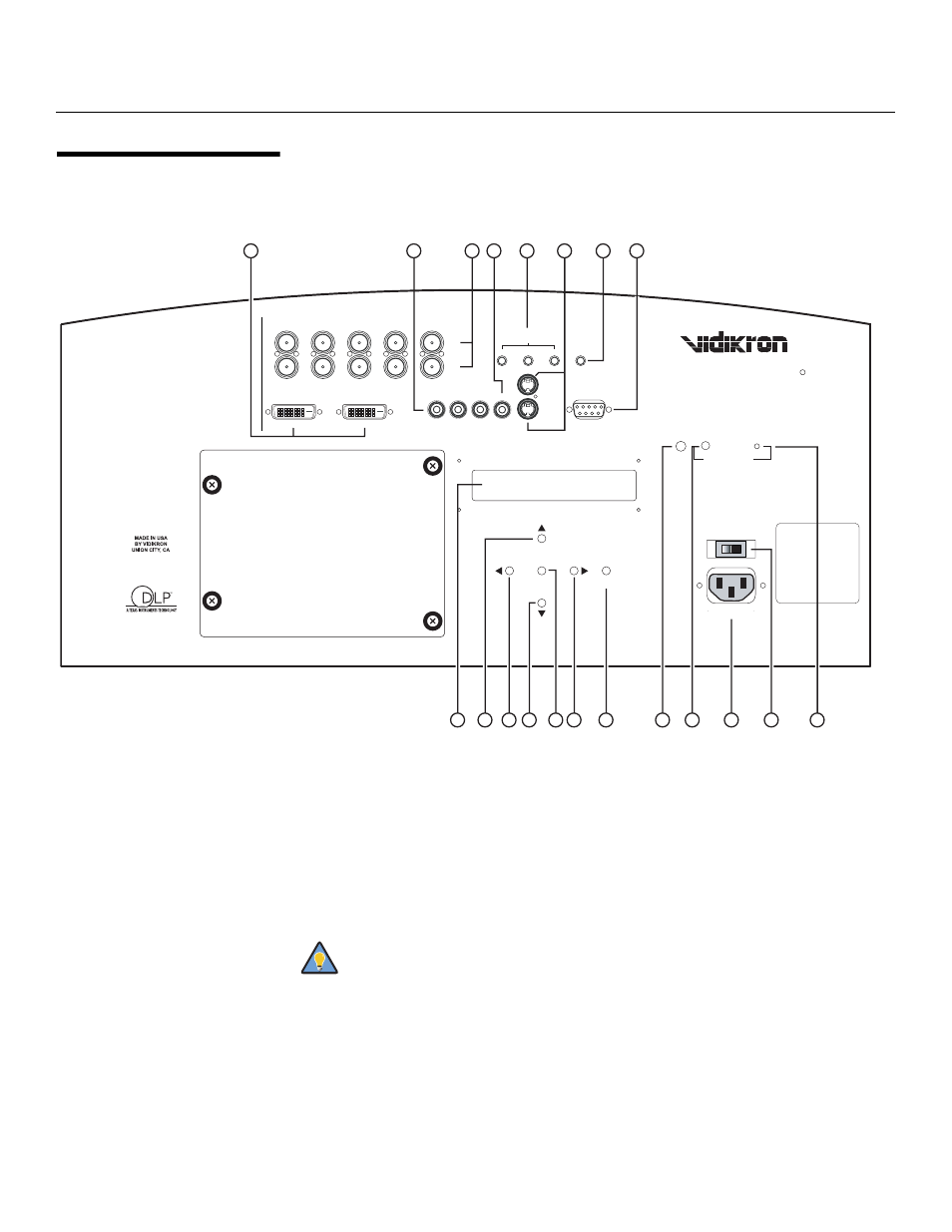
Vision 90 Rear Panel
Figure 2-2 shows the Vision 90 rear panel.
Figure 2-2. Vision 90 Rear Panel
1.
DVI 1 / DVI 2 (Digital)
Two, HDCP-compliant digital video inputs for connecting a DVD player or HD tuner with
a DVI or HDMI output.
2.
COMPONENT VIDEO (RCA connectors)
Standard Definition (480i/576i) Component (YPrPb) input. This is the input for
component video from sources such as DVD players.
3.
HD1 / HD2 (Analog BNC connectors)
Five, BNC connectors for connecting either RGB or component high-definition television
signals. The Vision 90 automatically detects the signal format: RGB(HV) or YPrPb, 480p,
720p, 480i, 576i or 1080i.
4.
COMPOSITE VIDEO INPUT
Standard composite video input for connecting a VCR, laser disc player or other
composite video source.
VISION MODEL 90
DIGITAL PROJECTOR
DVI 1
DVI 1
HD1
HD2
Y
G
G
Y
H
V
INPUTS
H
V
HD1
HD2
INPUTS
R
Pr
Pr
R
B
Pb
Pb
B
DVI 2
DVI 2
COMPONENT VIDEO
Pb
Pr
Y
COMPONENT VIDEO
Y
Pr
Pb
VIDEO
VIDEO
S-VIDEO 2
S-VIDEO 2
S-VIDEO 1
S-VIDEO 1
RS-232
CONTROL
RS-232
CONTROL
IR
IR
1
2
3
1
2
3
TRIGGERS
TRIGGERS
ENTER
MENU
ENTER
MENU
AC IN 110-240V 60HZ
AC IN 11
0-240V 60HZ
ON / OFF
OFF / ON
STANDBY / POWER
POWER / STANDBY
1
2
3
7
8
6
4
5
9
10
11
15
14
12
16
17
13
19
18
20
(LAMP COVER)
For best results, do not run your DVD player in progressive mode.
Tip